
Abstract
Aiming at the suspension fracture issue of hybrid cars produced by gravity casting, this paper primarily analyzes the application of squeeze casting in manufacturing hybrid car suspensions. During the design process of the squeeze casting die, modifications were made to address issues such as stuck squeeze pins. Specifically, the diameter of certain squeeze pins was adjusted from ϕ18 mm to ϕ16 mm, and the ingate was shifted 15 mm away from the casting’s maximum stress area. Parts produced using this mold passed destruction tests with high safety margins. While the tensile strength and yield strength of suspensions produced by metal gravity casting and squeeze casting are similar, the elongation of squeeze-cast parts is increased by over 100%, greatly reducing the risk of brittle fracture due to impact. In the pursuit of lightweight solutions, squeeze casting can serve as a substitute for forged aluminum and cast iron parts.
1. Introduction
As regulations on energy conservation, emission reduction, and fuel consumption become increasingly stringent, automotive lightweighting has garnered significant attention. This is particularly true for parts requiring high material yield strength and elongation, where squeeze casting (also known as liquid die forging) emerges as a highly suitable forming process.
2. Characteristics of Squeeze Casting Process
Squeeze casting involves applying high mechanical pressure (100 MPa) to liquid or semi-solid metal injected into a metal mold to shape and solidify it into a blank. Due to the simultaneous presence of high-pressure solidification and plastic deformation, parts produced by squeeze casting are devoid of defects such as shrinkage porosity and loose structures. After T6 heat treatment, their mechanical properties approximate those of forgings. Additionally, aluminum alloy parts can achieve radial dimensional accuracy of IT12~IT13, eliminating the need for feeding risers, simplifying processes, and enhancing alloy utilization rates, making them promising for automotive lightweighting.
Table 1. Comparison of Mechanical Properties of Parts
| Production Process | Tensile Strength (MPa) | Yield Strength (MPa) | Elongation (%) |
|---|---|---|---|
| Gravity Casting | 296 | 233 | 4.6 |
| Conventional Die Casting | 232 | 179 | 7.0 |
| Squeeze Casting | 322 | 254 | 10.8 |
Squeeze casting can be categorized into direct squeeze casting (pressure applied within the mold cavity) and indirect squeeze casting (pressure applied within the pressure chamber). Direct squeeze casting ensures effective pressure application, suitable for producing thick-walled and simple-shaped castings. Indirect squeeze casting offers greater flexibility, allowing for the production of complex-shaped castings with varying wall thicknesses, high dimensional accuracy, and excellent performance.
3. Application of Squeeze Casting in Automotive Suspensions
3.1 Material Selection for Squeeze Casting
Squeeze casting typically employs A356.2 aluminum alloy, equivalent to national standard ZL101A, with low Si and Fe content. The aluminum liquid requires modification treatment with Sr or Ti.
3.2 Application of Squeeze Casting in Suspensions
The brackets and arms of automotive suspensions are generally made of aluminum alloy die casting, with a few enterprises opting for ductile iron or aluminum alloy gravity casting for the arms. However, conventional die casting is prone to porosity, internal loose structures, and easy fracture, making it unsuitable for T6 heat treatment. Gravity casting parts exhibit low elongation and insufficient yield strength to meet hybrid vehicle load requirements. Ductile iron is susceptible to rust, affecting durability and reliability, and is relatively heavy,不利于environmental protection and vehicle weight reduction.
Hybrid vehicles experience significant impact loads during startups or acceleration and deceleration, which aluminum alloy gravity casting cannot withstand, leading to easy fracture. A certain hybrid vehicle’s suspension arm was initially designed using gravity casting ZL111. During tests involving continuous deceleration strips and rapid acceleration-deceleration cycles, suspension fractures caused the engine to sink.
Table 2. Mount Theory and Actual Vehicle Load and Fracture Situation
| Part | Right Mount | Left Mount | Load Direction | Maximum Load (kN) | Failure Force (kN) | Fracture Cases |
|---|---|---|---|---|---|---|
| X | Y | Z | ||||
| 40 | 33 | 7.4 | 26 | 4 (fractures) | ||
| Y | 33 | 27 | 2 (fractures) | |||
| Z | 7.4 | 26.7 | 1 | |||
| Left | X | Y | Z | 55 | 42 | |
| 41 | 28 | |||||
| 3.3 | 31.3 |
CAE simulation analysis was conducted using ABAQUS software, with A356.2 aluminum alloy tensile test data as material input. Results indicated that A356.2 alloy squeeze castings could withstand maximum real-vehicle loads, prompting the decision to switch to squeeze casting for suspension brackets and arms.
3.3 Experimental Research and Result Analysis
Tests were conducted on a road with continuous deceleration strips, with each set of three strips forming one group, and 11 groups constituting one test cycle. The vehicle accelerated rapidly at 40-50 km/h over the first and second strips, decelerated over the third and fourth, and so forth. Fractures occurred in both the suspension housing and arm during the seventh cycle.
Adopting the squeeze casting process for suspension brackets and arms involved a series of steps: aluminum liquid melting, refining and degassing, mold preparation, pouring, mold closing and pressing, extrusion, ejecting castings, sawing and grinding, T6 heat treatment, X-ray inspection, shot blasting, CNC machining, and inspection and packaging.
Destruction tests were conducted by fastening the suspension assembly to the test fixture and applying loads in the X, Y, and Z directions at a rate of 15 mm/min until fracture or the specified maximum load was reached.
Table 4. Test Results of Suspension Failure Force (Standard ≥ 56 kN)
| Sequence Number | Maximum Force (kN) | Judgment |
|---|---|---|
| 1 | 57.6 | OK |
| 2 | 41.0 | NO |
| 3 | 59.0 | OK |
| … | … | … |
| 7 | 48.0 | NO |
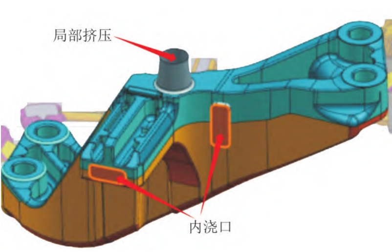
Microscopic analysis and energy spectrum analysis revealed that the main cause of shrinkage porosity at the fracture was the inability to effectively feed dendrite crystals due to long feeding distances during liquid metal cooling. Further analysis showed that the locally designed squeeze feeding structure experienced sticking or obstruction during production, resulting in insufficient local squeeze pressure. This led to shrinkage porosity or shrinkage cavities in the thick ingate area, causing an unsound structure and decreased strength.
4. Mold Improvement and Test Results
To address the issue of stuck squeeze pins, the diameter of certain squeeze pins was changed from ϕ18 mm to ϕ16 mm, and the ingate was moved 15 mm away from the maximum stress area.
Table 5. Failure Force Test Data of Parts After Improvement (Requirement ≥ 55 kN)
| Sequence Number | Failure Force (kN) |
|---|---|
| 1 | 84.0 |
| 2 | 82.4 |
| 3 | 81.8 |
| … | … |
| 20 | 81.9 |
After mold modifications, parts produced underwent destruction tests and all passed with high safety margins. X-ray inspection of the improved process’s microstructure showed no significant dark spots, microscopic shrinkage pores, or dendrite-shaped dark areas. The internal quality of the brackets was good, with shrinkage pores and porosity meeting ASTM E115 Grade 1 requirements.
5. Conclusion
The mounting brackets and supports for hybrid vehicles are produced through squeeze casting of A356.2 alloy, resulting in finer and denser internal metallurgical structures. After undergoing T6 treatment, their mechanical properties are comparable to those of forged aluminum alloys, offering significant advantages in lightweighting and cost-effectiveness. For the lightweighting of chassis components in new energy vehicles, a viable approach is to consider the use of A356.2 alloy squeeze castings as alternatives to forged aluminum alloys and ductile iron castings.