
In the evolving landscape of modern foundry practice, lost foam casting has transitioned from a novel technique to a mature and robust manufacturing process over the past half-century. Its application spectrum has broadened significantly, moving from simple components to intricate, high-integrity castings across a diverse range of alloys. This exploration is grounded in my direct experience and systematic investigation into adapting lost foam casting for a demanding application: large punch press machine beds or frames. Faced with market competition and rising material costs, the quest for a more economical alternative to traditional green sand molding for these substantial castings was paramount. Lost foam casting presented itself not merely as an alternative but as a strategic solution to enhance profit margins while meeting stringent quality requirements.
The advantages of employing lost foam casting for punch press beds are multifaceted and compelling:
- Production Flexibility: The process is equally adept at high-volume production runs and economical low-volume or single-piece production, offering significant versatility.
- Cost Efficiency: It often results in lower overall production costs compared to conventional sand casting, thereby increasing the value-added potential of the final product.
- Quality Attainment: Castings produced via lost foam casting can consistently achieve excellent surface finish, dimensional accuracy, and sound internal metallurgy that meet or exceed application demands.
- Market Viability: Given the substantial and continuous demand for punch press equipment, mastering an efficient casting method for their foundational components ensures strong market competitiveness.
In essence, lost foam casting represents a definitive developmental direction for the production of large, high-quality machine tool castings like press beds.
Analysis of the Casting: Characteristics and Foundry Challenges
The punch press machine bed is a quintessential large, heavy-sectioned casting. Its primary function is to provide massive structural rigidity and stability under dynamic operating loads. A typical geometry involves a box-like structure with thick-walled ribs, plates, and often integrated guideways or mounting pads.
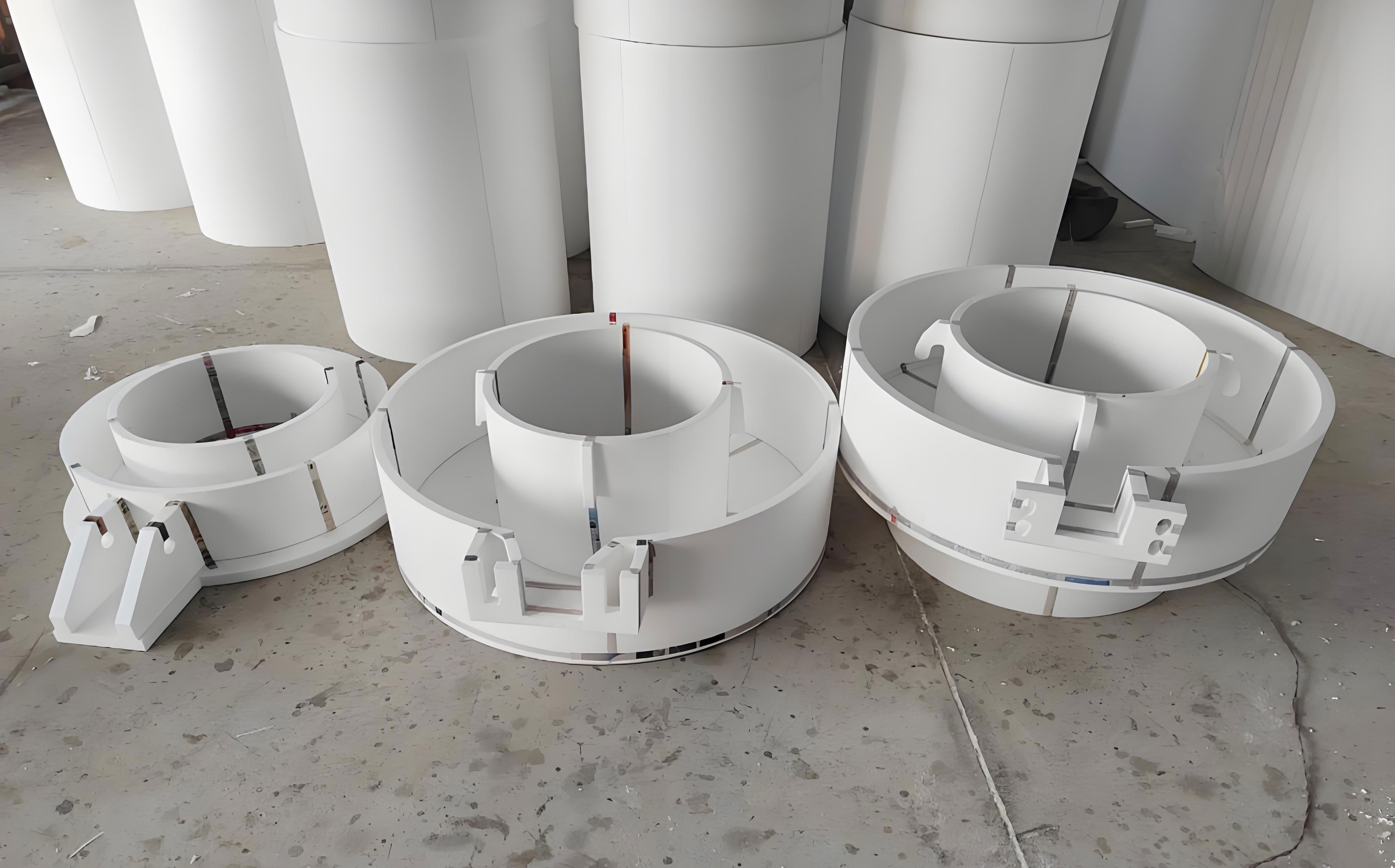
The specifications for such castings typically range through several sizes (e.g., corresponding to 35T, 50T, 63T, 80T, 100T, 125T press capacities). The material is generally grey iron, such as HT150 or HT200, with single casting weights ranging from approximately 1.1 to 5.0 tonnes. Key technical requirements include a good surface finish, machining allowances on specified areas, dimensional accuracy conforming to CT10-12 grades, and mass tolerance within CT9-11.
The foundational challenges in producing these castings via lost foam casting stem from their inherent geometry:
- Heavy Sections: Wall thicknesses are substantial, often exceeding 100 mm in critical areas, leading to prolonged solidification times.
- Significant Section Variation: The difference in thickness between adjacent walls (ribs vs. plates) can be extreme, sometimes over 100 mm, creating pronounced thermal gradients.
- Quality Imperatives: The castings require sound machining surfaces free from defects like gas holes, inclusions, or shrinkage. Mechanical properties, particularly impact strength tested from coupons taken from the casting itself, must be guaranteed.
These factors combine to make feeding, gas evolution management, and distortion control the central pillars of process design.
Critical Control of the Foam Pattern
The quality of the expendable foam pattern is the first and perhaps most critical determinant of final casting quality in lost foam casting. The pattern acts as the literal geometric template and is the source of the gas and residue that must be managed during metal pouring.
Raw Material Selection and Density
Expanded Polystyrene (EPS) is commonly used. The choice of bead pre-expansion grade and the final molded density of the foam pattern are crucial. Higher pattern density and carbon content lead to increased volume of liquid and gaseous decomposition products during metal fill. This can directly cause defects such as cold shuts, carbonaceous inclusions (lustrous carbon), and gas porosity. The relationship can be conceptually summarized by considering the mass of decomposable material per unit volume:
$$ m_{decomp} = \rho_{foam} \cdot V_{pattern} $$
where a higher foam density $\rho_{foam}$ increases $m_{decomp}$, raising the demand on the coating’s permeability and the sand system’s venting capacity. In practice, for these large iron castings, EPS with a controlled molded density in the range of 20-22 g/L has proven effective in balancing pattern strength for handling and minimizing carbon defect potential.
Pattern Fabrication and Quality Assurance
Patterns are typically produced by fusing pre-expanded beads in steam-heated aluminum tooling. The process parameters—steam pressure, time, and cooling—must be meticulously controlled to avoid “under-fusing” (weak, crumbly patterns) or “over-fusing” (shrunken, densified patterns). The goal is a uniform, smooth-surfaced pattern with fully fused beads and consistent density throughout. Specialized foam boards, fabricated to these exacting standards, are often used for large, flat sections or are cut and assembled into complex shapes. A summary of key pattern parameters is shown below:
| Parameter | Target Range / Requirement | Rationale & Impact |
|---|---|---|
| Primary Material | EPS (Specific grade for castings) | Balances cost, gas evolution, and surface finish. |
| Molded Density | 20 – 22 g/L | Provides adequate handling strength while limiting carbonaceous residue. |
| Bead Fusion | Complete, uniform | Prevents local weakness, surface roughness, and uneven degradation. |
| Pattern Drying | Essential before coating | Eliminates residual moisture which turns to steam explosively during pouring. |
Gating System Design and Pattern Assembly for Lost Foam Casting
The design of the gating and feeding system in lost foam casting is uniquely challenging because the metal front advances by displacing and degrading a solid foam pattern. The system must ensure calm, progressive filling to minimize turbulence, which can cause erosion of the unbaked coating and entrap pattern decomposition products. For large, heavy-section castings like press beds, the gates are typically larger in cross-sectional area compared to conventional sand casting to accommodate the high volumetric flow rate needed to maintain metal velocity ahead of the receding pattern front.
Several gating styles are considered:
Bottom Gating: Fills the mold cavity from the bottom up. Promotes a calm fill and good temperature gradient for directional solidification but can lead to oxidation and cooler metal at the top.
Step Gating: Introduces metal at multiple vertical levels. Can improve thermal distribution in tall castings but is more complex to design and assemble.
Side Gating: Metal enters from the side. Often used for flat or horizontal geometries.
For the punch press bed, with its thick, heavy sections requiring effective feeding, a bottom-gating system was selected. The ingates are strategically placed against the internal faces of the thickest vertical walls (the ribs). This placement serves a dual purpose: it introduces hot metal directly into the thermal centers that are last to solidify, and it uses the massive walls themselves as feeding paths. The gating system was designed with increased cross-sections to reduce metal velocity and ensure rapid fill. A schematic configuration is as follows:
- Ingates: 2 channels, each 160 mm x 20 mm (3200 mm² total area). Positioned on thick ribs.
- Runner / Distributor: Cross-section of 100 mm x 15 mm.
- Sprue: Diameter of 70 mm (≈3848 mm² area).
This design prioritizes a high flow rate with minimal friction. The assembly of the gating system to the main pattern must be seamless, using low-residue adhesives, and the joints must be smoothly faired to prevent turbulence initiation points.
The Science and Control of the Refractory Coating
The refractory coating in lost foam casting performs several life-critical functions: it provides a barrier between the molten metal and the sand, it must withstand metallostatic pressure and thermal shock, and it must allow the gaseous products of foam degradation to escape rapidly. The coating’s properties are a direct outcome of its formulation, mixing, and application.
Coating Composition and Target Properties
A typical coating is a water-based slurry containing:
Refractory Fillers: Zircon, fused silica, alumina, or mullite are common. Their particle size distribution (PSD) is key to permeability.
Binders: Both inorganic (e.g., clay, sodium silicate) and organic (e.g., latex, CMC) binders are used to provide green and fired strength.
Suspension Agents: To prevent settling and ensure consistent slurry viscosity.
Other Additives: Wetting agents, antifoams, biocides.
The ideal coating for large iron castings must exhibit a careful balance:
$$ \text{Coating Performance} = f(\text{Strength}, \text{Permeability}, \text{Refractoriness}) $$
Maximizing one property often compromises another. For instance, higher binder content increases strength but reduces permeability. The PSD of the filler is the primary lever for controlling permeability; a broader distribution can pack more densely, reducing permeability, while a narrower distribution of coarse particles increases it. The target is a coating with sufficient strength to resist metal erosion and enough permeability to vent gases without causing metal penetration into the sand. The slurry must be mixed thoroughly, often for 120 minutes or more under high shear, followed by continuous low-shear agitation to maintain consistency during use.
| Property | Target / Method | Consequence of Deviation |
|---|---|---|
| Viscosity (Flow Cup) | Consistent, application-specific (e.g., 40-50 sec) | Too thick: uneven coating, runs. Too thin: insufficient coating thickness. |
| Coating Thickness | 0.8 – 1.5 mm (after drying), controlled by dip time/viscosity | Too thin: metal penetration, burning-on. Too thick: reduced permeability, gas defects. |
| Permeability | High, but controlled (measured by specialized tests) | Too low: gas porosity, blows. Too high: metal penetration, rough casting surface. |
| Dry Strength | Sufficient to withstand sand filling and vibration | Low strength: coating cracks, metal penetration. |
Drying Protocol: A Non-Negotiable Step
After dipping, the coated patterns must be dried completely. Incomplete drying is a leading cause of pouring failures (violent recoil or “popping”) and gross gas defects. Drying must remove both free water (between particles) and bound water (from binders). For large patterns with thick sections, this is a prolonged process. A dedicated drying chamber with controlled temperature (45-50°C), dehumidification (relative humidity < 30%), and ample airflow is essential. Drying times can range from 24 hours for thinner sections to 72-96 hours for massive patterns. The drying kinetics can be approximated by a diffusion-limited process:
$$ \frac{\partial M}{\partial t} \approx D_{eff} \cdot \nabla^2 M $$
where $M$ is the moisture content and $D_{eff}$ is the effective moisture diffusivity, which increases with temperature. Proper support during drying is critical to prevent pattern distortion under its own weight.
Process Control in the Pouring Zone
The final stages of the lost foam casting process—sand filling, pouring, and solidification under controlled pressure—integrate all previous preparations. Meticulous control here is what transforms a well-made pattern into a sound casting.
Vibration Compaction and Sand System
The molding medium is unbonded, dry silica sand, typically AFS 40-70 grain fineness with rounded grains for optimal flowability and permeability. The sand must completely and uniformly fill all cavities within and around the complex foam assembly. This is achieved through a combination of sand raining and strategic vibration. The pattern must be positioned in the flask with a minimum sand margin (e.g., 250 mm) from all walls and the bottom. Vibration parameters—frequency (30-50 Hz), amplitude, and time—are optimized to achieve maximum sand density without causing pattern distortion or coating damage. The goal is to create a rigid, self-supporting mold that can withstand the metallostatic pressure.
The Pouring Operation and Vacuum Application
Melting is preferably done in medium-frequency induction furnaces for superior temperature and chemistry control compared to cupolas, especially for critical iron grades. Before pouring, a vacuum is applied to the sand flask. This vacuum serves multiple purposes: it rigidizes the loose sand, helping to resist metal pressure; it extracts air from the sand voids, creating a path for pattern gases; and it draws these gaseous decomposition products away from the advancing metal front through the permeable coating. For large iron castings, a vacuum level of 0.06-0.065 MPa (approx. 450-500 mm Hg) is typical.
The pour itself must be smooth and continuous. The ladle is positioned close to the pouring cup (~100 mm) to minimize stream oxidation and aspiration. The pouring rate is deliberately steady and moderately fast to maintain a consistent metal head pressure and to ensure the metal front does not stall, which would cause severe cold shuts. The sprue and pouring cup must remain full to prevent vortexing and air entrainment.
Pressure Holding and Solidification Control
Once pouring is complete, the vacuum is maintained for a critical “hold time.” This period is determined by the solidification dynamics of the heaviest sections. Releasing the vacuum too early, while the metal is still mushy or liquid in the core, can have two detrimental effects: internal porosity from expanding dissolved gases, and mold wall collapse leading to shape distortion or even a run-out. The required hold time $t_{hold}$ can be empirically related to the modulus of the heaviest section:
$$ t_{hold} \propto M^n \quad \text{where} \quad M = \frac{V_{casting}}{A_{casting}} $$
For thick-section grey iron castings like press beds, hold times of 10-15 minutes are common. After this period, the casting is sufficiently solid to maintain its shape, and the vacuum can be released safely for shakeout.
| Process Stage | Key Parameter | Typical Value / Control Method |
|---|---|---|
| Sand Filling | Vibration Frequency | 30 – 50 Hz |
| Vacuum Level | Applied Pressure | 0.060 – 0.065 MPa |
| Pouring | Pouring Temperature | Approx. 50-75°C above liquidus for iron |
| Pouring Style | Quick, smooth, and continuous | |
| Solidification | Vacuum Hold Time | 10 – 15 minutes (geometry dependent) |
Defect Analysis and Continuous Improvement in Lost Foam Casting
The successful implementation of lost foam casting relies on diagnosing and preventing characteristic defects. For large castings, the following are primary concerns:
- Carbon Defects (Inclusions): Caused by incomplete evacuation of liquid/gaseous styrene pyrolysis products. Mitigated by optimal foam density, high coating permeability, adequate vacuum, and correct pouring temperature.
- Gas Porosity: Results from trapped decomposition gases or moisture. Controlled by perfect pattern drying, effective vacuum draw through the coating, and proper gating to vent gases ahead of the metal.
- Folds/Cold Shuts: Occur when the metal front slows or splits due to low pouring temperature/speed, excessive foam density, or insufficient metal head pressure. Corrected by optimizing the gating ratio and pouring practice.
- Distortion: Can happen during pattern storage, coating drying (if poorly supported), or from non-uniform cooling. Managed by robust pattern handling, proper drying supports, and controlled cooling in the sand.
A rigorous inspection regime, including visual, dimensional, non-destructive testing (NDT) like ultrasonic testing for internal soundness, and destructive testing of coupons for mechanical properties, is essential for quality assurance and process feedback.
Conclusion
The transition to lost foam casting for the production of large punch press machine bed castings represents a significant technological and economic advancement. This process demonstrates a potent capability to deliver high-integrity, complex castings with superior surface finish and dimensional consistency compared to conventional green sand methods. The economic benefits are realized through reduced machining allowances, minimal core-making, lower cleaning costs, and enhanced production flexibility. The keys to success lie in a deep, systematic understanding and control of each sequential element: precise foam pattern engineering, scientifically formulated and applied coatings, rationally designed gating for controlled fill and feeding, and stringent process control during molding, pouring, and solidification. Lost foam casting, therefore, stands not just as an alternative, but as a forward-looking, competitive manufacturing philosophy for heavy-section ferrous castings in the demanding machine tool industry.