
In modern foundry practice, the evolution of lost foam casting has been pivotal for producing complex, near-net-shape components with high dimensional accuracy and excellent surface finish. The process, which involves evaporative pattern decomposition within unbonded sand under vacuum, presents unique advantages in flexibility and reduced machining requirements. Based on extensive engineering experience, I will delve into the detailed design, calculation, and operational characteristics of a high-capacity lost foam casting production line. This analysis will cover technical parameters, production scheduling, subsystem layouts, and the inherent benefits that drive its adoption, particularly for heavy-section castings like those used in engineering machinery.
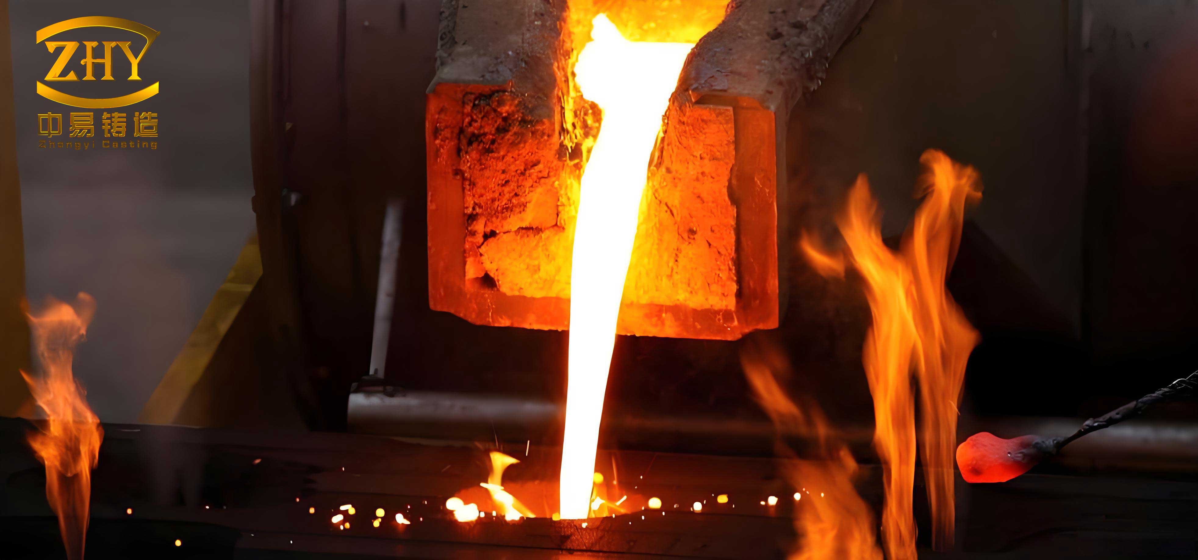
The core principle of lost foam casting (LFC) revolves around a sacrificial pattern, typically made of expanded polystyrene (EPS) or co-polymer, which is embedded in dry, unbonded sand within a ventilated flask. The mold is compacted via vibration, and a vacuum is applied to the sand mass to increase its rigidity. Molten metal is then poured directly onto the pattern, causing it to vaporize and be replaced by metal, precisely replicating the pattern’s geometry. This process eliminates the need for cores and parting lines, enabling designs previously impossible with conventional green sand or resin-bonded molding.
1. Foundational Process Requirements & Technical Specifications
The design of any lost foam casting line is fundamentally dictated by the product mix and desired output. For a line targeting an annual output of 12,000 tonnes of finished castings, the following baseline specifications are established.
| Parameter Category | Specification | Remarks / Rationale |
|---|---|---|
| Cast Material | Ductile Iron QT450 | Standard grade for high-strength, ductile engineering components. |
| Pattern Material | EPS or Co-polymer | Provides clean pyrolysis with minimal residue. |
| Molding Sand | Silica Sand | 30-40 AFS mesh size for optimal permeability and surface finish. |
| Minimum Wall Thickness | ≥ 5 mm | Ensures process viability for the intended product range. |
| Dimensional Tolerance | CT8 or better | As per ISO 8062, suitable for most industrial applications. |
| Pouring Weight per Casting | 500 kg | A key driver for flask sizing and metal handling. |
| Pouring Temperature | 1460 °C | Optimal for QT450, ensuring fluidity and proper pattern degradation. |
| Flask Internal Dimensions | 2100 L × 1200 W × 1200 H (mm) | Volume = 3.024 m³. Dictates pattern cluster size and sand consumption. |
| Target Production Cycle | 12 Flasks/Hour | The core “takt time” governing the entire line’s pacing. |
| Sand System Capacity | 60 t/h | Designed to support the continuous molding cycle. |
| Vacuum System | Automatic Docking | For consistent, efficient vacuum application during pouring and cooling. |
2. Production Rhythm and Capacity Calculations
The heart of production line design lies in synchronizing all subsystems to meet the target output. The calculations below demonstrate the logical flow from annual target to hourly requirements for metal and sand.
2.1 Metal Requirement Calculation
The first step is to determine the net metal needed per hour, accounting for yield losses.
Given:
Annual Target (Net Castings): $A_c = 12,000$ tonnes
Operating Days/Year: $D_y = 300$ days
Hours per Shift: $H_d = 8$ hours
Castings Yield (Quality): $Y_q = 95\% = 0.95$
Metal Yield (Pouring Efficiency): $Y_m = 85\% = 0.85$
The net casting production rate required is:
$$ R_{net} = \frac{A_c}{D_y \times H_d} = \frac{12,000 \text{ t}}{300 \times 8 \text{ h}} = 5.0 \text{ t/h} $$
To achieve this net rate, the required molten metal throughput ($R_{metal}$) is:
$$ R_{metal} = \frac{R_{net}}{Y_q \times Y_m} = \frac{5.0 \text{ t/h}}{0.95 \times 0.85} \approx 6.19 \text{ t/h} $$
We round this to $R_{metal} = 6.2$ t/h for design purposes.
2.2 Flask Cycle and Number Calculation
With a known pouring weight per casting ($W_c = 500$ kg = 0.5 t), the number of flasks processed per hour ($N_f$) is:
$$ N_f = \frac{R_{metal}}{W_c} = \frac{6.2 \text{ t/h}}{0.5 \text{ t/flask}} = 12.4 \text{ flasks/h} $$
Practically, this is rounded down to $N_f = 12$ flasks/h to establish a stable, achievable cycle time. This sets the core production beat or “takt time” ($T_t$):
$$ T_t = \frac{60 \text{ min}}{N_f} = \frac{60}{12} = 5.0 \text{ minutes/flask} $$
Every 5 minutes, a flask must complete a critical process step (molding, pouring, cooling discharge).
2.3 Sand System Sizing Calculation
The sand system must circulate and condition enough sand to fill the flasks continuously. The key parameters are flask volume ($V_f = 3.024$ m³), sand fill factor ($k_s \approx 0.8$), and sand bulk density ($\rho_s \approx 2.0$ t/m³).
Sand required per flask ($S_f$):
$$ S_f = V_f \times k_s \times \rho_s = 3.024 \text{ m}^3 \times 0.8 \times 2.0 \text{ t/m}^3 \approx 4.84 \text{ t} $$
Total sand circulation rate ($R_s$) for $N_f = 12$ flasks/h:
$$ R_s = S_f \times N_f = 4.84 \text{ t/flask} \times 12 \text{ flasks/h} \approx 58.1 \text{ t/h} $$
The system is therefore designed for a nominal capacity of $R_s^{design} = 60$ t/h, providing a ~3% safety margin.
| Calculated Parameter | Symbol | Value | Unit |
|---|---|---|---|
| Net Casting Production Rate | $R_{net}$ | 5.0 | t/h |
| Required Molten Metal Rate | $R_{metal}$ | 6.2 | t/h |
| Target Flasks per Hour | $N_f$ | 12 | flasks/h |
| Production Takt Time | $T_t$ | 5.0 | min |
| Sand per Flask | $S_f$ | ~4.84 | t |
| Sand System Design Capacity | $R_s^{design}$ | 60 | t/h |
3. Production Line Layout and Subsystem Description
The layout is configured as an open, straight-line flow with pallet car transfer, which offers superior flexibility compared to closed-loop continuous lines. This modular approach allows segments like the cooling conveyor to be extended easily based on the solidification requirements of different castings in a lost foam casting process.
3.1 Overall Layout Philosophy
The line is essentially divided into three parallel tracks: two for pouring/cooling and one for empty flask return. Flasks are mounted on pallet cars, which are indexed through the stations by hydraulic push cylinders. Transition cars move flasks between parallel tracks. This “straight-line with transfer” design decouples the cycle times of different segments, allowing the cooling section, for instance, to have a multiple of the basic 5-minute takt time without affecting the molding pace.
3.2 Sand Preparation and Reclamation System
The sand system is the circulatory system of the lost foam casting line. Its primary functions are sand cooling, screening, and transportation. The designed 60 t/h flow undergoes a rigorous process:
- Discharge & Primary Separation: The poured flask is moved to a shakeout station where a hydraulic flask turnover device discharges the entire sand and casting package onto a vibrating grid. This initial step removes the majority of sand from the castings.
- Sand Screening & Conveying: Sand falls onto a vibrating conveyor/screen that removes large debris and residual pattern clusters. The sand is then elevated via bucket elevators.
- Critical Sand Cooling: Given the high pouring temperature (1460°C), sand returning from shakeout can exceed 100°C. Effective cooling is non-negotiable, as hot sand compromises pattern stability during molding and worker safety. The system employs a two-stage sand temperature conditioner, each stage containing multiple, sequential heat exchanger units. The cooling efficiency can be modeled by a simplified energy balance:
$$ \dot{m}_s C_{p,s} (T_{in} – T_{out}) = \dot{Q}_{removed} $$
where $\dot{m}_s$ is sand mass flow rate, $C_{p,s}$ is the specific heat of sand, and $T_{in}$ and $T_{out}$ are the sand temperatures entering and leaving the conditioner. - Final Screening & Storage: Cooled sand passes through a final linear screen for fine purification and is conveyed to an overhead storage hopper above the molding stations, completing the loop.
- Integrated Metal Removal: A magnetic head pulley on the final conveyor belt continuously extracts fine metallic particles (gates, runners, broken castings) that passed through the initial screens, ensuring sand purity for the lost foam casting process.
| Equipment | Primary Function | Key Feature |
|---|---|---|
| Hydraulic Flask Turner | Automated sand discharge | Improves safety and consistency over manual methods. |
| Vibrating Shakeout/Screen | Separates castings from bulk sand | First stage of debris removal. |
| Two-Stage Sand Cooler | Reduces sand temperature | Multiple heat exchanger modules for high efficiency. |
| Linear Vibrating Screen | Final sand purification | Removes fine ashes and degraded sand grains. |
| Magnetic Separator | Removes ferrous contaminants | Essential for maintaining sand quality in long-term operation. |
3.3 Molding Station Design
The molding sequence is critical for achieving uniform and adequate compaction around complex patterns. The station is automated for repeatability:
- Bottom Sand Fill & Pre-compaction: The empty flask on its pallet car is positioned under a rain-type sand filler. A controlled amount of sand is admitted and compacted using a single-axis vibration table to create a level base.
- Pattern Placement: The pre-assembled and coated foam pattern cluster is placed onto the leveled sand bed.
- Main Fill & 3D Compaction: The flask is moved to a three-dimensional compaction station. Sand is filled around the pattern while the flask is subjected to programmable, multi-directional vibrations. The use of three independent variable-frequency drives (VFDs) allows precise control of frequency ($f$), amplitude ($A$), and direction to optimize packing density ($\rho_{pack}$) without causing pattern distortion. The process can be tuned for different pattern geometries.
$$ \text{Compaction Result} \propto \int (A(f) \cdot f) \, dt $$
across X, Y, and Z axes. - Finishing: After compaction, a plastic film is placed over the sand surface, a layer of loose sand is added, and the pouring cup is positioned.
3.4 Pouring, Cooling, and Vacuum System
The poured flask is indexed into one of the parallel pouring lines. Key features here include:
- Automatic Vacuum Docking: As the pallet car stops at a pouring station, an automated mechanism connects the flask’s vacuum ports to the plant’s central vacuum system. This ensures a perfect seal every time, which is vital for mold rigidity and fume extraction during the lost foam casting pour.
- Segmented Fume Extraction: Each pouring station is equipped with its own dedicated hood and extraction duct. Electronically controlled butterfly valves modulate airflow based on which station is active, maximizing capture efficiency of pyrolysis gases and minimizing energy consumption for the environmental control system.
- Flexible Cooling Conveyor: The length of the cooling line is a design variable. The required cooling time ($T_{cool}$) for a 500 kg ductile iron casting can be estimated based on modulus and heat transfer. The line length ($L_{cool}$) is then:
$$ L_{cool} = N_{cool} \times (L_{flask} + \text{Spacing}) $$
where $N_{cool}$ is the number of cooling stations ($N_{cool} = T_{cool} / T_t$). The straight-line layout makes extending $L_{cool}$ straightforward.
4. Operational Advantages and Economic Rationale
The design choices embodied in this lost foam casting production line translate into distinct operational and economic benefits that solidify its value proposition for high-volume precision casting.
4.1 Enhanced Automation and Control
The integration of PLC (Programmable Logic Controller) with a touch-screen HMI (Human-Machine Interface) creates a centrally monitored and controlled system. Key parameters like vibration profiles, sand gate opening times, vacuum levels, and conveyor indexing are programmed and stored. The system includes comprehensive fault diagnostics, alerting operators to issues like motor overload, low hydraulic pressure, or sand flow blockage, minimizing downtime. This level of control is essential for maintaining the consistency required in high-quality lost foam casting.
4.2 Improved Sand System Efficiency
The two-stage cooling and two-stage screening (vibrating screen + linear screen) ensure that sand returned to the molding station is not only cool but also exceptionally clean. This directly impacts casting surface quality and reduces the incidence of sand-related defects. The integrated magnetic separator protects downstream equipment and further enhances sand longevity. The automated sand handling from shakeout to storage minimizes manual labor and associated variability.
4.3 Superior Environmental Management
The lost foam casting process generates smoke and gases during pouring. The line’s design addresses this proactively. The dedicated, valve-controlled fume extraction at each pouring station ensures fumes are captured at the source with high efficiency. Combined with the central bag-house dust collector for the sand system and any melting furnace operations, the total plant emissions are effectively controlled, meeting stringent environmental standards and improving the workplace atmosphere.
4.4 Flexibility and Scalability
The straight-line pallet car system is inherently modular. If product mix changes require longer cooling times or additional processing stations (e.g., for in-line coating or inspection), the line can be lengthened without major structural redesign. This future-proofs the capital investment. The use of pallet cars, as opposed to flasks with attached wheels, provides more stable and precise positioning for critical operations like vacuum docking and sand filling.
| Benefit Category | Specific Advantage | Impact |
|---|---|---|
| Quality & Yield | Precise 3D compaction control; Clean, cooled sand. | Higher dimensional accuracy (CT8), better surface finish, reduced scrap. |
| Productivity | Automated cycle; 12 flasks/hour steady pace. | Achieves designed 12,000 t/year output with high asset utilization. |
| Labor & Safety | Automated sand handling, flask transfer, fume capture. | Reduced manual labor, lower physical strain, safer working environment. |
| Maintenance & Uptime | PLC-based monitoring with fault diagnosis. | Predictive maintenance, faster troubleshooting, increased line availability. |
| Process Flexibility | Modular straight-line layout; Tunable vibration parameters. | Easier adaptation to new casting geometries and future capacity expansion. |
4.5 Economic Performance
The ultimate validation of a lost foam casting line is its return on investment. The described line, by achieving high automation and consistent process control, delivers significant cost savings per tonne of casting. Reduced labor content, lower scrap rates, and minimized post-casting machining (due to near-net-shape capability) are the primary drivers. The efficient sand reclamation system, with its high cooling capacity, ensures sand is a stable, reusable medium rather than a consumable expense. When operational, such a line transforms the lost foam casting process from a specialized technique into a robust, high-volume manufacturing solution capable of competing with and often surpassing traditional molding methods for complex components.
In conclusion, the engineering of a modern, high-capacity lost foam casting production line represents a sophisticated synthesis of metallurgical science, mechanical design, and industrial automation. By meticulously calculating production rhythms, designing robust and efficient subsystems for sand and mold handling, and integrating advanced control and environmental management, such a line achieves the reliability and quality necessary for competitive manufacturing. The flexibility inherent in its layout ensures it can adapt to evolving product demands, making it a cornerstone technology for foundries specializing in precision ferrous castings for the engineering, automotive, and heavy machinery sectors.