
In the pursuit of engineering components that exhibit superior strength, toughness, and reliability under demanding service conditions, the interplay between advanced metallurgical heat treatments and precision foundry processes is paramount. My experience in component design and failure analysis consistently underscores that the final properties of a critical part are not determined by a single operation but are the culmination of synergistic effects from initial alloy design through final heat treatment. This article delves into a specific case that exemplifies this synergy: the application of intercritical hardening (often termed subcritical quenching) to enhance the properties of a steel, coupled with a meticulously engineered sand casting process for a complex aluminum alloy component. The goal is to elucidate the underlying mechanisms and provide a detailed, quantitative framework for practitioners. A recurrent theme will be the critical considerations for producing high-integrity sand casting parts, where design, gating, feeding, and metallurgy must converge.
Part I: Metallurgical Enhancement through Intercritical Hardening
The core challenge with many high-strength low-alloy (HSLA) steels is their susceptibility to temper embrittlement, a phenomenon where toughness decreases after exposure to specific temperature ranges during tempering. Intercritical hardening, a heat treatment involving quenching from a temperature between the lower (Ac1) and upper (Ac3) critical points, has proven highly effective in mitigating this. The mechanism is multifaceted, involving microstructural refinement and modification of carbon distribution.
1.1 Mechanism of Embrittlement Suppression
When a steel is quenched from the intercritical (α+γ) region, the resulting microstructure consists of martensite (from the austenite phase) and undissolved ferrite. The martensite formed from this carbon-enriched austenite has a higher carbon content than the steel’s nominal average. During subsequent tempering, this leads to a more pronounced and coarser dispersion of carbide precipitates. The consequence is twofold, as described by the following sequence:
$$C_{M}^{‘} > \bar{C}_{steel}$$
$$Q_{temp} \propto f(C_{M}^{‘}, T_{temp}, t_{temp})$$
where \(C_{M}^{‘}\) is the carbon content in the intercritically-formed martensite, \(\bar{C}_{steel}\) is the nominal steel carbon content, and \(Q_{temp}\) represents the quantity and coarseness of temper carbides.
This extensive carbide precipitation depletes the carbon remaining in solid solution within the ferritic regions. Consequently, upon slow cooling from the tempering temperature, the driving force for reprecipitation of fine, strong-pinning carbonitride phases (e.g., Cr-rich carbonitrides) from the ferrite is significantly reduced. This weakens the so-called “hard pinning” effect on mobile dislocations.
$$N_{pin} = g([C]_{sol}, [Cr]_{sol}, T_{cool})$$
Here, \(N_{pin}\) denotes the number density of potent pinning points, which is a function of the solute carbon (\([C]_{sol}\)) and chromium (\([Cr]_{sol}\)) concentrations in ferrite during cooling. With lower \([C]_{sol}\), \(N_{pin}\) decreases.
The reduced pinning allows for greater dislocation mobility under applied stress, facilitating plastic deformation and thereby improving toughness and lowering the ductile-to-brittle transition temperature (DBTT). Furthermore, the presence of the fine, stable ferrite phase inherently refines the final austenite grain size prior to quenching, leading to a refined martensitic structure. This grain refinement strengthens and purifies grain boundaries, reducing the segregation of embrittling elements like phosphorus and tin. The combined effects are summarized in the table below.
| Microstructural Feature | Effect of Intercritical Hardening | Consequence on Properties |
|---|---|---|
| Prior Austenite Grain Size | Significantly Refined | Higher strength (Hall-Petch), cleaner boundaries. |
| Martensite Carbon Content | Higher than nominal | Promotes coarse temper carbides. |
| Solute Carbon in Ferrite | Lower after tempering | Reduces hard-pinning carbonitrides. |
| Dislocation Pinning Force | Weakened | Enhanced dislocation mobility, better toughness. |
| Grain Boundary Chemistry | Purified (less segregation) | Suppresses intergranular fracture, raises DBTT. |
Thus, the primary mechanisms for suppressing high-temperature temper embrittlement via intercritical hardening are: (1) Grain refinement, (2) Strengthening and purification of grain boundaries, and (3) Alleviation of the hard pinning effect on mobile dislocations. An optimized process sequence, such as an initial normalizing at 920°C followed by intercritical quenching from 790°C and tempering at 650°C, has been shown to yield an excellent combination of strength and toughness.
Part II: Precision Engineering of Complex Sand Casting Parts
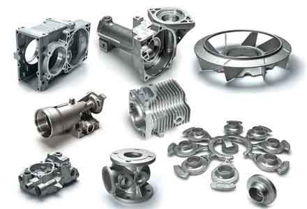
The principles of microstructural control extend seamlessly into the realm of casting. The production of sound, high-performance sand casting parts, especially for safety-critical applications, demands an analytical approach to process design. Let us consider the detailed sand casting process for a high-pressure cylinder body, a component where internal soundness and pressure tightness are non-negotiable.
2.1 Component Analysis and Gating Strategy
The cylinder body features a complex geometry with a large flange containing multiple precision seal grooves and an attached cylindrical section. The alloy is an Al-Si-Mg type with a pronounced tendency for oxidation and gas pick-up. The primary design challenge is to ensure the absolute integrity of the seal groove areas, which are machined subsequently and must be free from porosity, inclusions, or micro-shrinkage. Four potential gating schemes were analyzed, as critically compared below:
| Scheme | Orientation | Advantages | Disadvantages | Feasibility |
|---|---|---|---|---|
| 1. Vertical (Flange Down) | Flange at bottom | – | Seal grooves on top; difficult molding/pouring; poor thermal gradient. | Poor |
| 2. Horizontal (Side Gating to Cylinder) | Part split in cope/drag | Easy molding; grooves on side; good access for risers. | Severe metal splash between sections causing dross. | Fair |
| 3. Horizontal (Side Gating to Flange) | Part split in cope/drag | Easy molding; grooves on side; good thermal gradient; no splash. | Long metal flow path; potential for localized overheating. | Good |
| 4. Horizontal (Dual Gating) | Part split in cope/drag | All above advantages; controlled filling via stepped runner. | Slightly more complex runner design. | Excellent |
Scheme 4 was selected. It employs a stepped runner system with two ingates: a primary ingate into the flange and a secondary ingate into the lower section of the cylinder. This design ensures the flange fills first, eliminating splash. Once the metal level surpasses the cylinder’s lowest point, the secondary ingate activates, allowing simultaneous, controlled filling from two points, minimizing flow length and temperature gradients.
2.2 Rigging System Design: Risers, Chills, and Gating Calculations
The design of feeding and gating systems for such sand casting parts follows systematic engineering calculations.
Riser Design using the Modulus Method: Risers are sized based on the thermal modulus (Volume/Surface Area) of the sections to be fed. For a cylindrical side riser, the neck modulus \(M_{neck}\) must satisfy \(M_{neck} > M_{casting}\). The riser volume must provide sufficient liquid feed metal. For the flange (approximated as a plate):
$$M_{flange} \approx \frac{Thickness}{2} = \frac{50mm}{2} = 25mm$$
A cylindrical riser with a modulus \(M_{riser} = 1.2 \times M_{flange} = 30mm\) would have a diameter \(D_{riser} \approx 60mm\). For geometrical compatibility, a rectangular riser of equivalent modulus is often used. Similar calculations are performed for other hot spots.
| Hot Spot Location | Approx. Modulus (mm) | Riser Type | Calculated/Dimension (mm) |
|---|---|---|---|
| Main Flange | 25 | Rectangular | 100 (L) x 60 (W) x 80 (H) |
| Connecting Plate | 18 | Rectangular | 80 (L) x 40 (W) x 80 (H) |
| Cylinder End | 15 | Cylindrical | Diameter: 40, Height: 80 |
Chill Design: External chills are placed against the thick flange sections and internal cylinder walls to promote directional solidification towards the risers and to create a fine-grained, dense structure in critical seal groove areas. Chill thickness is typically equal to the adjacent casting section thickness for single-sided chills.
Gating System Calculation: An open, pressurized system with filters is designed. The total choke area (usually at the sprue base or filter) is calculated based on the Bernoulli equation and empirical factors:
$$A_{choke} = \frac{W}{\rho \cdot t \cdot C_d \cdot \sqrt{2gH}}$$
Where:
\(W\) = Pour weight (kg), \(\rho\) = Metal density (kg/m³), \(t\) = Desired fill time (s),
\(C_d\) = Discharge coefficient (~0.8 for metallic filters), \(g\) = Gravity (m/s²), \(H\) = Effective metallostatic head (m).
For the cylinder body (W ~ 40 kg, target t ~ 15 s, H ~ 0.2 m):
$$A_{choke} \approx \frac{40}{2700 \cdot 15 \cdot 0.8 \cdot \sqrt{2 \cdot 9.81 \cdot 0.2}} \approx 4.7 \times 10^{-4} m^2 = 470 mm^2$$
This area is distributed in a typical ratio for aluminum: \(A_{sprue} : A_{runner} : A_{ingate} = 1 : 2 : 1.5\). Ceramic foam filters with an increased effective area are placed in the runner to reduce turbulence and filter inclusions.
2.3 Process Parameters and Quality Assurance
Strict control over melting, treatment, and pouring is essential for premium sand casting parts. The following parameters are typical for such an Al-Si-Mg alloy component:
| Process Stage | Key Parameter | Target Value / Specification |
|---|---|---|
| Melting & Treatment | Melt Temperature | 720 – 750 °C |
| Degassing | Hexachloroethane or N₂ Rotor, 5-10 min | |
| Grain Refinement / Modification | Al-Ti-B, Al-Sr additions per standard practice | |
| Molding | Coating on Chills | Resin + Zircon Sand coat to prevent fusion |
| Filter Placement | In runner, upstream of first ingate | |
| Pouring | Pouring Temperature | 690 – 710 °C |
| Technique | Ladle pour with skim bob; maintain sprue full |
The designed stepped runner successfully sequences the filling. Initial metal flows through the primary ingate into the flange. Once the mold cavity fills to the level of the secondary ingate, metal begins flowing into the cylinder section, resulting in a calm, non-turbulent fill. The combination of chills, risers, and a well-calculated gating system ensures soundness, particularly in the critical seal areas. This process has demonstrated a consistent yield of over 95% for first-quality sand casting parts.
Conclusion: The Integrated Engineering Approach
The journey from a raw alloy to a reliable high-performance component is a testament to integrated materials engineering. As demonstrated, the enhancement of steel toughness via intercritical hardening relies on a deep understanding of carbon redistribution, precipitate kinetics, and dislocation dynamics. Similarly, the production of flawless, complex sand casting parts in aluminum alloys demands a rigorous, calculative approach to fluid dynamics, heat transfer, and solidification feeding.
The synergy lies in recognizing that these are not isolated fields. The metallurgist must understand the casting process that creates the initial microstructure, often containing segregation and unique as-cast phases. The foundry engineer must appreciate how subsequent heat treatments like intercritical hardening, tempering, or solution treatment will alter the microstructure and dimensions of the casting. For instance, residual stresses from quenching or the presence of specific micro-segregations can significantly influence the final component’s response to service loads.
Therefore, the optimal design and manufacturing of critical components—whether they are high-strength steel forgings subsequently heat-treated or intricate aluminum sand casting parts—require a holistic view. It necessitates the continuous feedback of data between process steps, the application of fundamental principles expressed through engineering mathematics, and an unwavering focus on the quantitative control of every variable. This integrated methodology, combining advanced metallurgy with precision casting practice, remains the cornerstone for achieving the demanding performance benchmarks of modern engineering applications.