
Sand casting molds mostly belong to the blank mold of casting products, and the template is a part and the most important part of the whole sand casting mold. In this paper, the casting process adopts two box modeling. When designing the sand casting mold template, the upper and lower sand boxes are divided by the parting surface. Two single-sided aluminum templates of the upper and lower boxes need to be made to make the upper and lower sand molds. In the mold design of sand casting, it is necessary to restore the solid features such as draft angle and fillet of the three-dimensional model of tooling in actual production. Where draft features are 3 to 4 degrees and fillets are 3 to 5 degrees. Because only the design and processing simulation of sand casting mold template are done, and the template is a punch, the modeling module of UG is still used in the three-dimensional modeling design of sand casting mold template, which can meet the design requirements and is convenient and fast, without using the mold Wizard of UG NX injection mold module specially used for mold design.
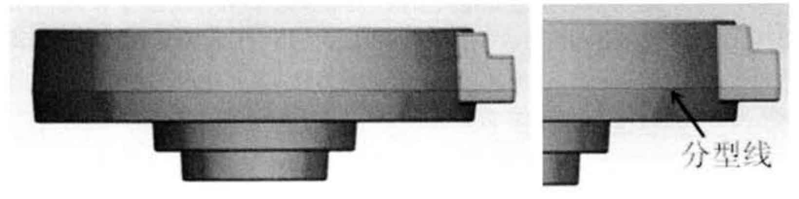
The three-dimensional solid modeling and parting line position of the casting blank after restoring the geometric features of the casting blank in actual production, such as draft angle and chamfer, are shown in Figure 1.
In the UG NX assembly module, each component is relatively independent and cannot be summed into a geometric solid model for modification. In this case, when you want to modify the geometric characteristics of a component in the assembly model, you need to modify the PRT file of a single component by repeatedly switching the opened and working components, In this way, the process of modifying the three-dimensional model of tooling is very cumbersome and inefficient, and it is difficult to achieve the desired modification effect because each component cannot be combined into a geometric entity during Boolean operation.
Here, after repeated attempts, it is found that all features of the assembled tooling are selected and exported to the Parasolid text file. Then, import the generated x T format file into UG NX. After this series of operations, the components can be combined into a geometric entity by Boolean operation for various modeling operations. At the same time, the geometric features can be modified directly at each position of the 3D model. This method greatly simplifies the steps of 3D modeling of sand casting mold template.
Here, the three-dimensional models of the upper and lower sand mold templates obtained after the solid model modification of the assembled gating and riser system and sand core are shown in Figure 2.
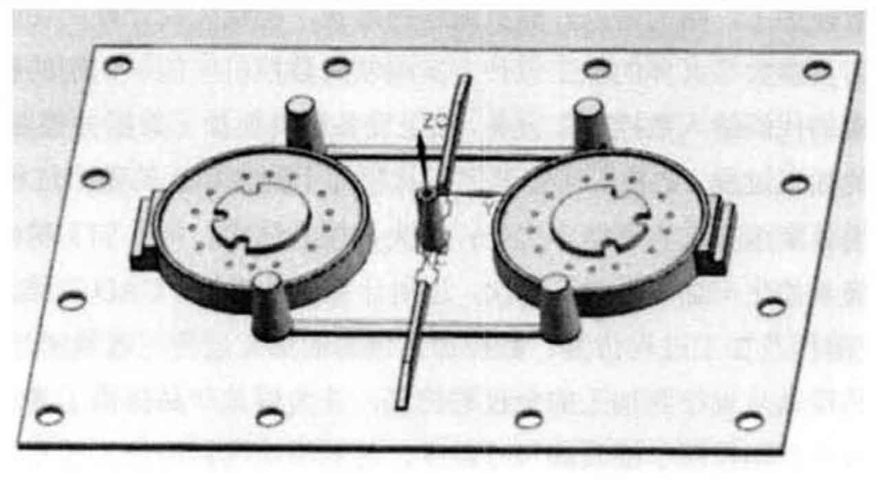
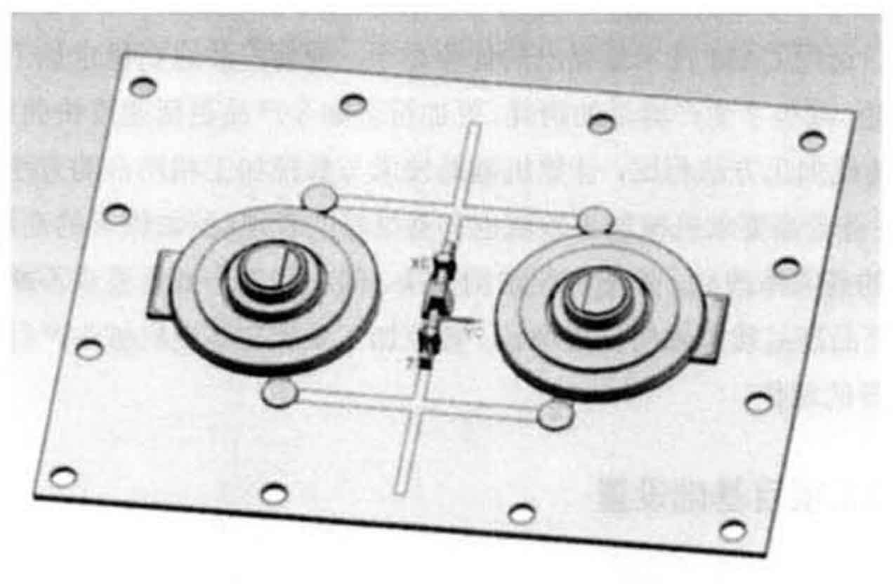
For the upper sand casting mold template in Figure 2, in order to reduce the size of aluminum alloy blank during processing, the sprue part higher than the upper plane of the riser is cut off, and the groove is opened at the cutting surface of the sprue. When the template is used for sand molding, the model with shape and size such as the cut sprue part is inserted into the circular groove to make it butt joint into the shape of tooling sprue, This will help to reduce the waste of blank and tool wear.