
1. Steel castings manufacturer conduct trial production of anvil castings
1.1 Production of foam pattern
The pattern is designed in blocks according to the initial process to facilitate the production and assembly of foam patterns. After cutting each part, use a glue stick to bond it and assemble it according to the drawing requirements.
1.2 Styling
Using water glass sand for shaping. Place the assembled foam pattern on the bottom plate, place cold iron on the upper surface of the pattern, cover the sand box, fill the sand box with molding sand, and place the side cold iron according to the optimized process in the molding process. After the molding sand has gone through the foam pattern, manually compact the sand mold. After the sand mold hardens, destroy the foam pattern and take it out, then check the surface quality of the sand mold, and repair the damaged parts. Apply alcohol based zircon powder coating on the surface of the mold.
1.3 Melting and pouring
Mix and melt according to the composition requirements of the product, and pour after passing the chemical composition test in front of the furnace. During the pouring process, when the liquid level rises to one-third of the height of the riser, it is poured by the riser and poured 2-3 times at intervals of 3-5 seconds. Place a heating cover inside the riser to delay its solidification and promote the filling process.
1.4 Product post-processing
The post-treatment process for anvil castings by steel castings manufacturer. The steel castings manufacturer found severe sand sticking at the circular arc position of the anvil casting after sand cleaning, as shown in Figure 1. No obvious crack defects were found in the magnetic particle inspection after annealing, but linear defects were found at the inner runner after quenching; In addition, a long linear defect was found at the arc position on one side of the inner cavity. After removing the surface metal, further observation revealed that the crack was deeper. Even after cleaning at a depth of 20 mm, it could not be completely removed, and during the defect removal process, a smaller hole like defect was also found in that area. The product can only be scrapped in the end.
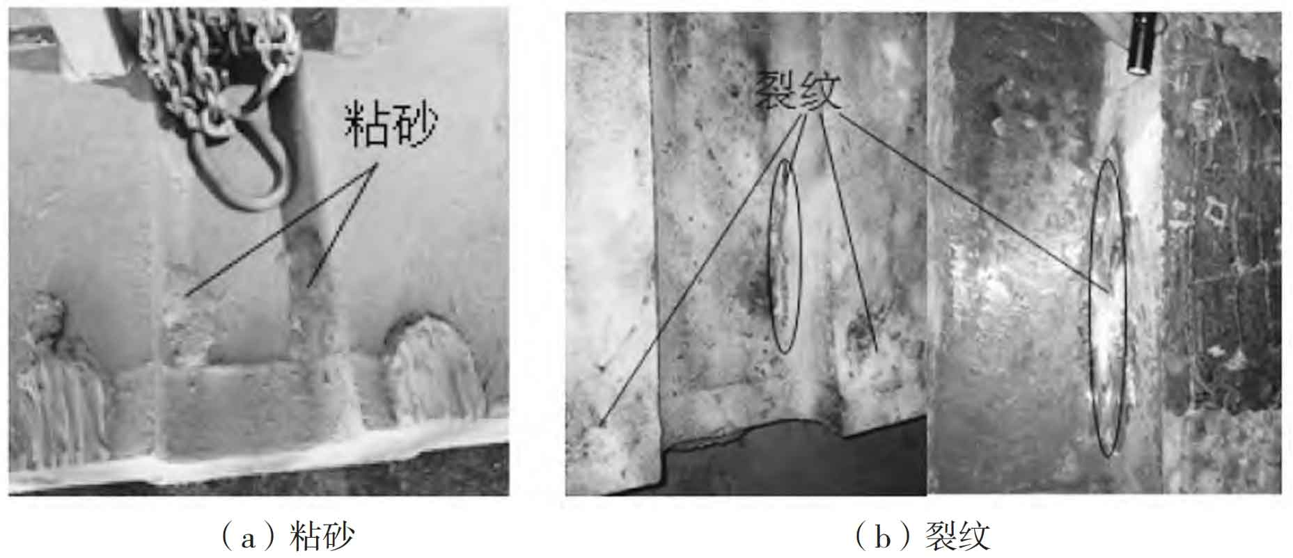
Analyzing the cause, the steel castings manufacturer found that the crack defect at the inner gate of the anvil seat casting is due to the residual metal cut by the inner gate being removed by air gouging. Air gouging will create a high-temperature area around it, which will then generate significant stress during the cooling process, ultimately leading to the occurrence of cracks. The reason for the occurrence of cracks at the circular arc of the inner cavity is firstly due to the presence of defects such as pores and shrinkage holes in this area, indicating that the steel castings manufacturer did not sufficiently supplement and shrink the anvil seat casting; Secondly, during the quenching process, significant stress is generated, which is concentrated around the pores, causing cracks to propagate along the defect zone.
Through tracking the production process of anvil castings by steel castings manufacturer and analyzing photo data, there are two obvious reasons that may lead to the generation of shrinkage stress. First, the steel castings manufacturer has designed more cold irons for the anvil casting process, and the side cold irons are placed at most three layers. Because of the foam pattern molding, the side cold irons can only be placed while filling sand during the molding process. The actual placement of cold iron differs from the process design. Secondly, the position of the middle riser is biased towards one side, resulting in the early closure of the filling and contraction channel on the other side.
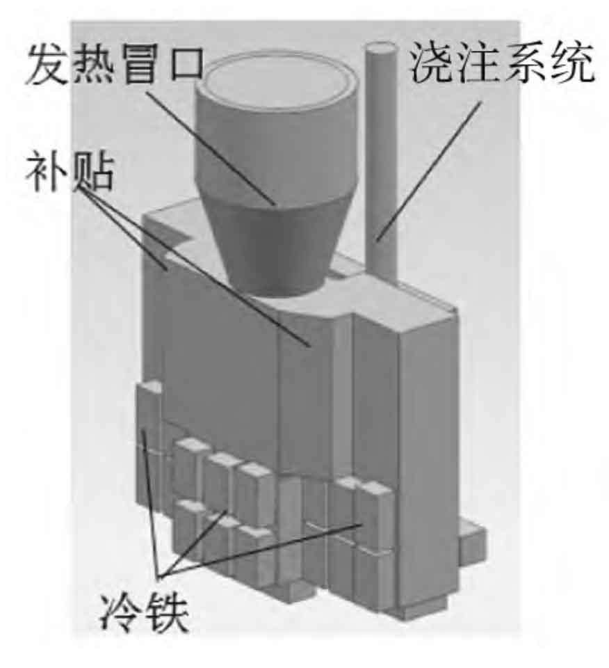
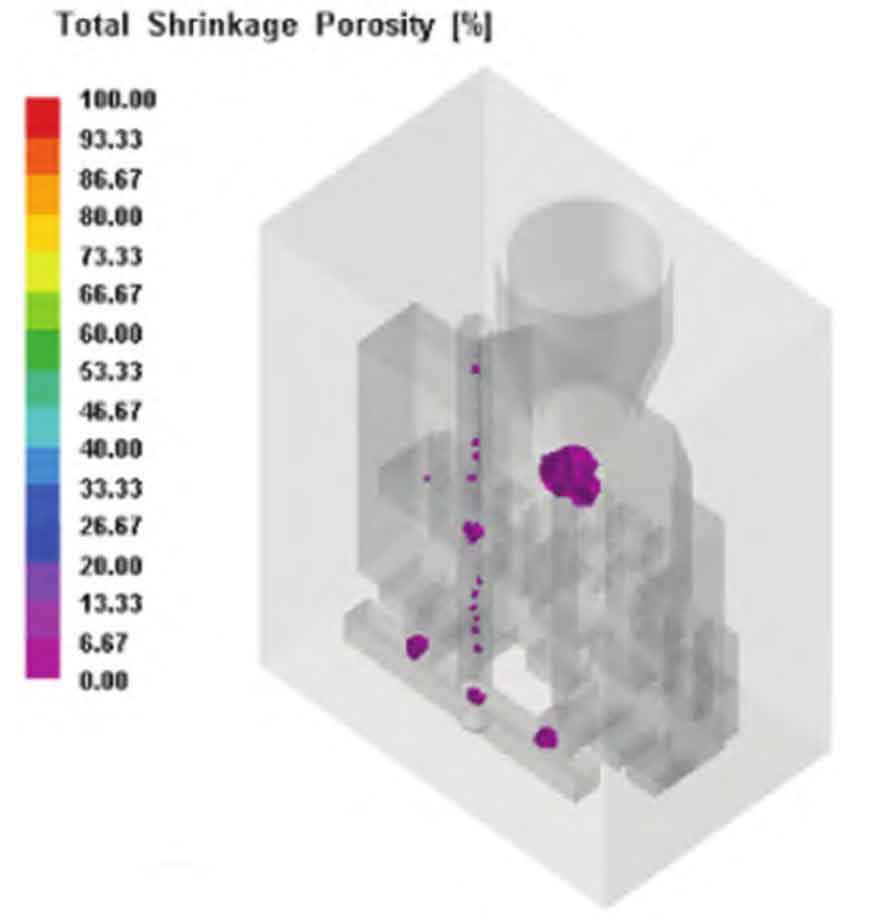
The experiment conducted numerical simulation of solidification on the actual production process again, and the scheme is shown in Figure 2. The simulation results of the solidification process are shown in Figure 3. From the figure, it can be seen that during the solidification process, shrinkage defects were formed on the upper part of the anvil casting by the steel castings manufacturer.
2. Optimization of Anvil Casting Process by Steel Castings Manufacturer
2.1 Process optimization plan
For the sand sticking defect in the circular arc area, on the one hand, increase the radius of the circular arc during pattern making; On the other hand, in the shaping process, by strengthening the method of manually assisted compaction, the compactness of the molding sand in the circular arc area is increased, and the thickness of the coating layer in that area is also increased.
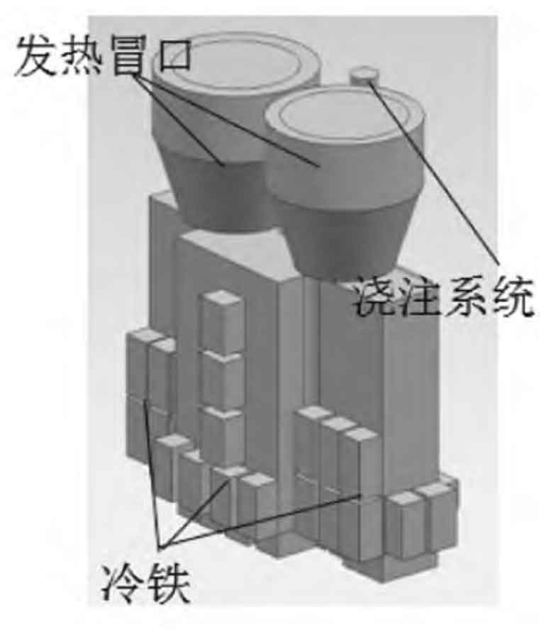
For defects at the inner runner, a residual height of 10-15 mm should be left when removing the remaining part of the inner runner, and the remaining part should be removed during the machining process. Regarding the inner arc shrinkage defect, considering on-site operational factors, the process has been redesigned, increasing the riser from one in the middle to two symmetrical ones; Remove riser subsidies and reduce machining workload; Adjust the position of the cold iron and pay attention to its placement during styling to ensure compliance with the requirements of the process design. The process yield of the improvement plan is 61.8%. The optimized process plan is shown in Figure 4.
2.2 Optimizing Process Solidification Simulation
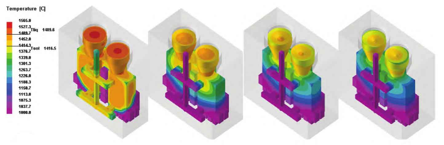
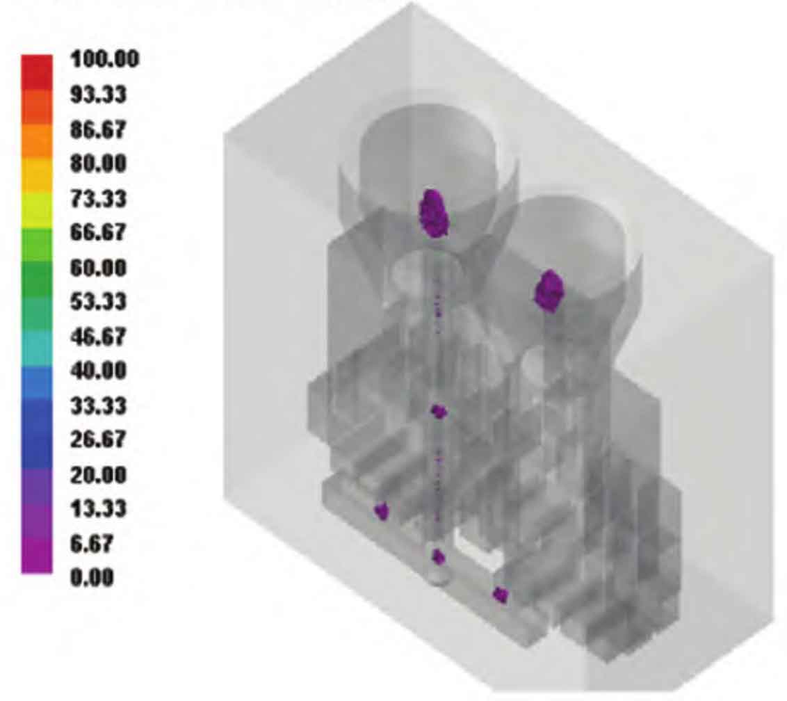
Simulate the optimized process using ProCAST software, with consistent parameter settings as before. Figure 5 shows the distribution of temperature field during the solidification process of anvil castings by steel castings manufacturer. Steel castings manufacturer have achieved sequential solidification of the anvil castings from bottom to top by placing cold iron at the bottom and side positions, where the temperature drops the fastest and solidification occurs first. The steel castings manufacturer symmetrically placed two rows of cold iron in the middle of the two risers of the anvil casting, causing the steel castings manufacturer to form two independent hot spots on the anvil casting. As solidification proceeds, the final solidification occurs in the two risers, and the steel castings manufacturer does not produce an isolated liquid phase region on the anvil casting part. Figure 6 shows the distribution of shrinkage and porosity in the solidified anvil castings by the steel castings manufacturer. It can be seen from the figure that the defects are concentrated in the pouring system and riser part, while the steel castings manufacturer did not find any defects in the anvil castings. From the numerical simulation results, it can be seen that the optimized steel castings manufacturer has achieved good results in the anvil casting process.
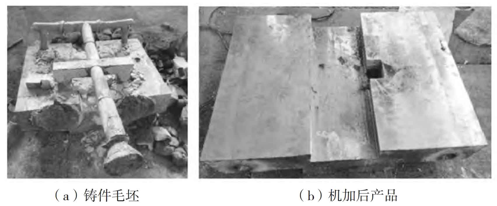
3. Production validation
Production was carried out according to the improved process plan, and the steel castings manufacturer cleaned, heat treated, non-destructive tested, machined, and inspected the anvil castings to meet the requirements. The product is shown in Figure 7, with the left side being the product blank and the right side being the finished product after machining.
(1) Numerical simulation technology was used to assist steel castings manufacturer in the design and optimization of anvil casting process, and UG 3D solid modeling, polystyrene foam and foam cutting machine were used to make patterns. Rapid preparation of ester hardened sodium silicate sand mold was realized, and high-quality ZG45 anvil casting was formed by melting casting, which improved the product development progress by 30%.
(2) During the initial process design, three layers of cold iron were installed on the side. However, due to inconvenient operation during the actual molding process, the product developed obvious shrinkage defects, which could only be scrapped. In the process optimization, the feasibility of operation was fully considered, the number of risers was increased, and the difficulty of operation was reduced. After trial production, the product met the technical requirements.