
As a researcher and practitioner in the field of metal casting, I have witnessed firsthand the transformative impact of numerical simulation technologies. Casting, fundamentally a process transitioning from solid to liquid and back to solid, is fraught with uncontrollable factors, particularly during liquid filling and solidification. However, with the advent of numerical simulation, we can now pre-set controllable parameters—such as molding sand properties in sand casting, pouring temperature, and chemical composition—in software like ProCAST to simulate flow and solidification. This allows for process optimization based on simulation outcomes, moving casting production from experience-based to scientifically guided practices. Numerical simulation of casting filling and solidification has reached an engineering practical stage, enabling effective prediction of defects like shrinkage porosity, gas entrapment, and misruns before actual production, thereby ensuring quality, shortening trial cycles, and reducing costs.
In this article, I will delve into the application of numerical simulation across various casting methods, with a particular emphasis on sand casting, as it remains a widely used and versatile process. I will explore how simulation aids in optimizing工艺 parameters, predicting defects, and enhancing overall efficiency. Through detailed explanations, tables, and mathematical formulations, I aim to provide a comprehensive overview of this critical technology.
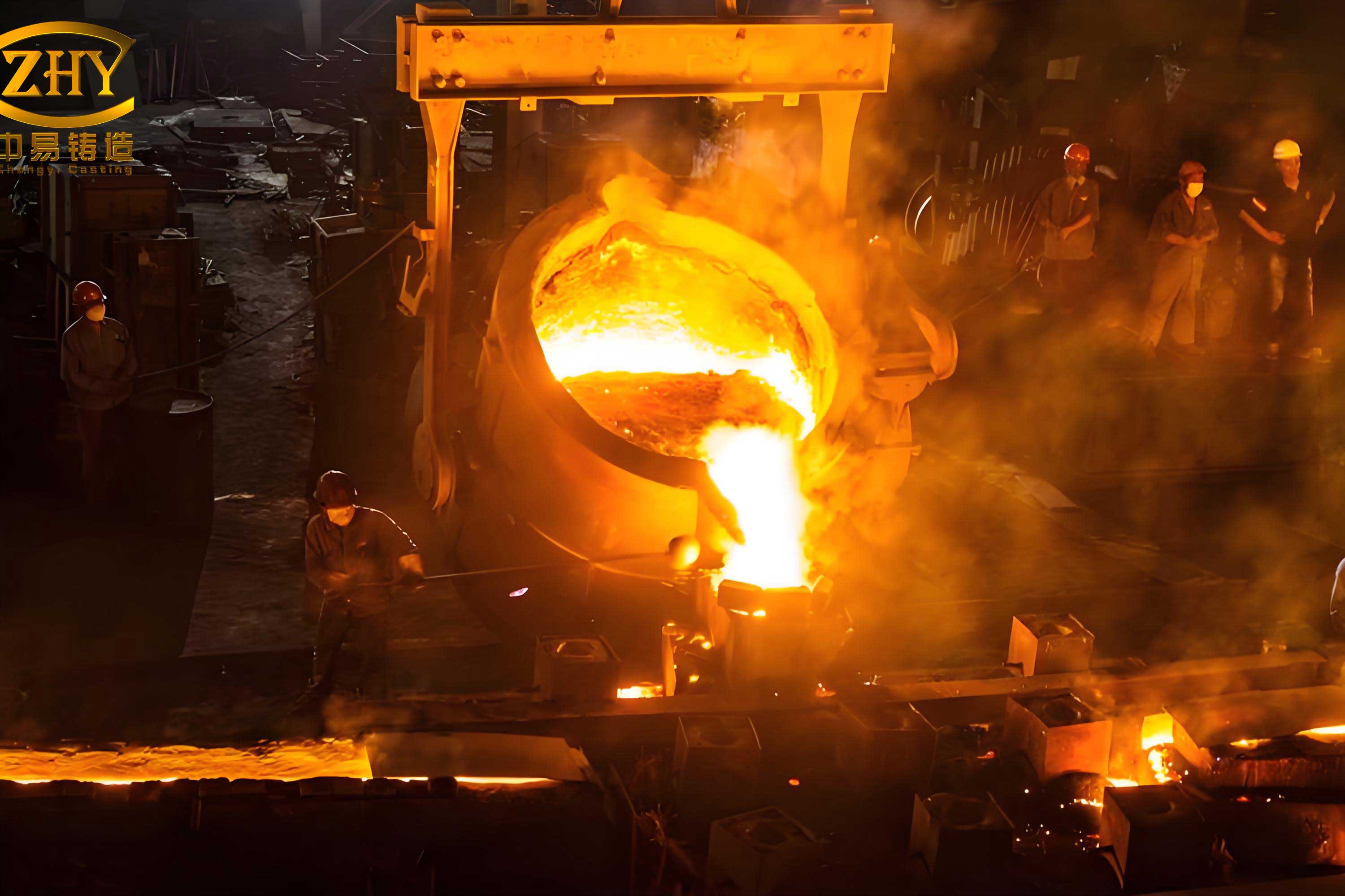
The core of numerical simulation lies in building mathematical models that represent physical phenomena. For sand casting and other methods, these models typically involve governing equations for fluid flow, heat transfer, and stress analysis. Key equations include the Navier-Stokes equations for momentum conservation during filling, and the heat conduction equation for solidification. For instance, the energy equation governing temperature distribution can be expressed as:
$$ \rho c_p \frac{\partial T}{\partial t} = \nabla \cdot (k \nabla T) + Q $$
where \( \rho \) is density, \( c_p \) is specific heat, \( T \) is temperature, \( t \) is time, \( k \) is thermal conductivity, and \( Q \) represents internal heat sources. In sand casting simulations, this equation is solved numerically to predict temperature fields during solidification, helping identify hot spots prone to defects.
Similarly, for fluid flow during mold filling in sand casting, the incompressible Navier-Stokes equations are often employed:
$$ \nabla \cdot \mathbf{v} = 0 $$
$$ \rho \left( \frac{\partial \mathbf{v}}{\partial t} + \mathbf{v} \cdot \nabla \mathbf{v} \right) = -\nabla p + \mu \nabla^2 \mathbf{v} + \rho \mathbf{g} $$
Here, \( \mathbf{v} \) is velocity, \( p \) is pressure, \( \mu \) is dynamic viscosity, and \( \mathbf{g} \) is gravitational acceleration. Solving these equations allows us to visualize flow patterns, detect turbulence or vortex formation—common in sand casting—and optimize gating systems for smoother filling.
To illustrate the practical application, let’s consider sand casting in detail. Sand casting involves creating molds from sand, and numerical simulation helps optimize parameters before physical tooling. Below is a table summarizing typical input parameters for simulating a sand casting process:
| Parameter Category | Specific Parameters | Typical Values/Ranges | Impact on Simulation |
|---|---|---|---|
| Mold Material (Sand) | Permeability, thermal conductivity, density | Permeability: 1-10 Darcy; Conductivity: 0.5-1.5 W/m·K | Affects gas escape and heat transfer during solidification in sand casting. |
| Metal Alloy | Chemical composition, pouring temperature, latent heat | e.g., Aluminum A356: Si 7%, Mg 0.3%; Pouring temp: 700-750°C | Determines fluidity, solidification range, and defect formation. |
| Process Conditions | Pouring time, filling velocity, ambient temperature | Pouring time: 5-30 s; Velocity: 0.5-2 m/s | Influences flow behavior and thermal gradients. |
| Geometric Factors | Part geometry, gating system design, riser placement | Varies based on component; often optimized via simulation | Critical for ensuring complete filling and feeding in sand casting. |
In sand casting, simulation typically encompasses four main aspects: (1) liquid flow simulation (filling), (2) solidification simulation, (3) microstructure simulation, and (4) defect analysis and prediction. For filling simulation, we track the advancing liquid front and calculate velocity fields to identify issues like air entrapment or cold shuts. Solidification simulation focuses on temperature evolution over time, using equations like the heat conduction equation above. Microstructure simulation may involve models such as the cellular automaton method to predict grain growth, which is crucial for mechanical properties. Defect prediction leverages criteria functions; for example, shrinkage porosity in sand casting can be estimated using the Niyama criterion:
$$ G / \sqrt{\dot{T}} $$
where \( G \) is temperature gradient and \( \dot{T} \) is cooling rate. Regions with values below a threshold indicate potential shrinkage.
To further elucidate, consider a vertical flaskless sand casting process. Before mold making, we simulate gravity casting using actual production conditions. The simulation reveals flow instabilities, such as vortices at 1.7 seconds into filling, which could lead to slag inclusion or gas defects in sand casting. By adjusting gating designs, we achieve laminar flow by 7.2 seconds. Solidification simulation shows temperature contours at 35 seconds and 686 seconds, highlighting thermal gradients that guide riser optimization to improve yield and minimize defects like shrinkage cavities. This iterative optimization in sand casting reduces development time and costs significantly.
Another critical area is low-pressure die casting, commonly used for wheel hubs. Here, simulation aids in designing cooling systems—like water-cooling circuits—to control mold temperature cycles. The process involves transient thermal analysis over multiple cycles. A key aspect is modeling the periodic heating and cooling of the mold, which affects defect formation and cycle time. The heat transfer during mold opening and closing can be described by:
$$ \frac{\partial T}{\partial t} = \alpha \nabla^2 T $$
with \( \alpha = k/(\rho c_p) \) as thermal diffusivity. Simulation inputs include boundary conditions like inflow temperature, initial mold temperature, and cooling channel settings. Below is a table summarizing simulation steps for low-pressure casting of wheels:
| Simulation Phase | Key Activities | Parameters Considered | Outputs |
|---|---|---|---|
| Pre-processing | 3D geometry meshing, boundary condition setup | Mesh size: 0.5-2 mm; Inlet velocity: 0.1-0.5 m/s; Cooling channel positions | Discretized model ready for computation |
| Numerical Computation | Solving coupled flow-thermal equations over cycles | Cycle time: 60-120 s; Mold material properties; Alloy thermophysical data | Temperature fields, flow patterns, solidification sequences |
| Post-processing | Visualization of results, parameter adjustment | Contour plots of temperature, velocity vectors, defect probability maps | Optimized cooling strategy, reduced cycle time, defect mitigation |
In sand casting, similar multi-cycle analyses can be applied for high-volume production to ensure process stability. For instance, simulating several consecutive pours in sand casting helps assess mold degradation or thermal equilibrium.
High-pressure die casting (HPDC) presents unique challenges due to rapid filling and intense thermal cycling. Numerical simulation here predicts mold temperature distributions and thermal stresses, which cause fatigue failure. The thermal stress model often couples heat transfer with mechanical deformation, using equations like:
$$ \sigma = E \alpha_T \Delta T $$
where \( \sigma \) is stress, \( E \) is Young’s modulus, \( \alpha_T \) is thermal expansion coefficient, and \( \Delta T \) is temperature difference. Simulation in HPDC allows digital prototyping of molds, optimizing gate and vent designs before costly manufacturing. Compared to sand casting, HPDC involves higher pressures and shorter timescales, but the simulation principles remain analogous—modeling flow, heat transfer, and defect formation. For example, gas entrapment defects, common in both sand casting and HPDC, can be predicted using volume-of-fluid methods to track air pockets.
To quantitatively compare the impact of simulation across casting methods, consider the following table on cost and time savings:
| Casting Method | Typical Defects Addressed | Simulation-Driven Optimization | Estimated Reduction in Trial Cycles | Cost Impact (CI Improvement) |
|---|---|---|---|---|
| Sand Casting | Shrinkage, porosity, sand inclusion, mistruns | Gating/riser design, pouring temperature optimization | 40-60% | High (due to lower mold costs and scrap reduction) |
| Low-Pressure Casting | Shrinkage, coarse grains, cycle time inefficiencies | Cooling system design, pressure curve adjustment | 30-50% | Medium (saves energy and improves yield) |
| High-Pressure Die Casting | Hot tearing, gas porosity, mold wear | Mold thermal management, venting optimization | 50-70% | Very high (mold costs are substantial) |
The integration of numerical simulation into sand casting is particularly beneficial due to the process’s adaptability and widespread use. For example, in sand casting, we can simulate various molding sand types—such as green sand or resin-bonded sand—to evaluate their effects on heat transfer and defect formation. The governing equations often include source terms for sand properties. A generalized form for energy balance in a sand casting mold might be:
$$ \rho_m c_{p,m} \frac{\partial T_m}{\partial t} = \nabla \cdot (k_m \nabla T_m) + h_{int}(T_c – T_m) $$
where subscript \( m \) denotes mold (sand), \( c \) denotes casting metal, and \( h_{int} \) is interfacial heat transfer coefficient. This equation highlights the coupling between metal and sand in sand casting simulations.
Moreover, advanced simulation in sand casting incorporates stochastic models to account for uncertainties in sand properties or pouring conditions. For instance, Monte Carlo methods can be used to simulate variations in sand permeability, affecting gas defect probabilities. The defect prediction accuracy in sand casting is enhanced by such approaches, making the process more controllable.
In terms of software implementation, tools like ProCAST, MAGMA, and ANSYS Fluent are employed. These solvers discretize the equations using finite element or finite volume methods. For sand casting, mesh generation must capture complex geometries of sand molds and cores. A typical mesh quality metric is the aspect ratio, kept below 5 for accuracy. Simulation outputs include time-series data, which can be summarized using performance indices. For example, a filling efficiency index \( \eta_f \) for sand casting can be defined as:
$$ \eta_f = \frac{\text{Volume filled without turbulence}}{\text{Total volume}} \times 100\% $$
Optimization aims to maximize \( \eta_f \) through iterative design changes.
Looking at specific case studies, in sand casting of engine blocks, simulation reduces shrinkage defects by optimizing riser placement based on solidification gradients. The temperature gradient \( G \) and cooling rate \( \dot{T} \) are computed from simulation results, and the Niyama criterion is applied pixel-by-pixel to generate defect maps. Similarly, for thin-walled sand castings, flow simulation helps prevent cold shuts by adjusting pouring temperatures and gate sizes.
Beyond traditional sand casting, numerical simulation also supports innovative processes like lost foam casting or vacuum-assisted sand casting. In all cases, the core principles remain: modeling physics, validating with experiments, and iterating for improvement. The table below outlines key mathematical models used in sand casting simulation:
| Physical Phenomenon | Governing Equation/Model | Parameters Specific to Sand Casting | Numerical Solution Technique |
|---|---|---|---|
| Fluid Flow (Filling) | Navier-Stokes equations with free surface tracking (VOF method) | Sand mold wall roughness, binder decomposition gases | Finite Volume Method (FVM) with implicit time stepping |
| Heat Transfer (Solidification) | Transient heat conduction with phase change (enthalpy method) | Sand thermal properties, air gap formation at metal-sand interface | Finite Element Method (FEM) using adaptive meshing |
| Defect Prediction | Criteria functions (e.g., Niyama, Lee criterion for porosity) | Sand permeability effects on gas porosity, feeding resistance | Post-processing of temperature and pressure fields |
| Microstructure Evolution | Cellular automaton or phase field models | Cooling rates influenced by sand mold thickness and composition | Coupled with heat transfer solver at microscale |
In conclusion, numerical simulation has become indispensable in modern casting, especially for sand casting, where it turns uncontrollable factors into manageable variables. Through physics-based modeling, we can predict and mitigate defects, optimize工艺 parameters, and achieve substantial cost and time savings. As computer hardware and software advance, simulation will grow more accurate and accessible, further revolutionizing sand casting and other casting methods. The future lies in integrating simulation with real-time process control and additive manufacturing for molds, pushing the boundaries of what’s possible in metal casting.
Throughout this discussion, I’ve emphasized sand casting due to its prevalence and the significant benefits simulation brings. From gravity-fed sand casting to low-pressure and high-pressure die casting, numerical simulation provides a digital twin of the process, enabling proactive optimization. The mathematical frameworks and tables presented here underscore the technical depth involved, and I encourage further exploration into this dynamic field to harness its full potential for industrial innovation.