
In the manufacturing of critical components such as end caps for railway engines, spheroidal graphite cast iron, often referred to as ductile iron or nodular iron, is widely used due to its excellent mechanical properties, including high tensile strength and good ductility. However, during the casting process, defects like shrinkage, porosity, or inclusions can occur, leading to exposed flaws that compromise the integrity of the castings. To mitigate scrap losses and ensure reliability, welding repair becomes a viable solution under specific conditions. This article, based on my extensive experience in casting quality management, delves into the comprehensive control flow for welding repair of spheroidal graphite cast iron end cap castings, emphasizing manual arc cold welding techniques. I will outline the establishment of Welding Procedure Specifications (WPS), Welding Procedure Qualification Records (WPQR), and critical parameter selections, aiming to standardize the process, enhance first-pass qualification rates, reduce risks, and achieve assembly and service requirements. Throughout this discussion, the term ‘spheroidal graphite cast iron’ will be frequently highlighted to underscore its significance in this context.
The welding repair of spheroidal graphite cast iron presents unique challenges due to its inherent material characteristics. Spheroidal graphite cast iron typically contains high carbon and impurity levels, such as sulfur and phosphorus, which can lead to poor weldability, including susceptibility to cracking, white iron formation, and hardened zones in the heat-affected area. For end cap castings made of grade QT500-7, which demands a tensile strength over 500 MPa and elongation of 7%, any repair must ensure that the welded region retains at least 80% of the base metal’s mechanical properties. This necessitates a meticulous approach to welding process control. In this article, I will explore the weldability of spheroidal graphite cast iron, detail the step-by-step control flow, and provide insights into parameter optimization, supported by tables and formulas to encapsulate key data.
To begin, understanding the weldability of spheroidal graphite cast iron is crucial. The material’s composition, as shown in Table 1, includes carbon in the range of 3.4–3.8%, silicon at 1.9–2.5%, and low manganese, phosphorus, and sulfur. These elements influence the formation of graphite spheroids and the matrix structure, but during welding, they can cause issues like carbide precipitation or martensite transformation if not controlled. The welding process for spheroidal graphite cast iron often involves cold welding to avoid distortion and residual stresses associated with preheating. However, cold welding requires precise parameter management to prevent defects. The fundamental equation for assessing weldability can be expressed in terms of carbon equivalent (CE), which for spheroidal graphite cast iron is critical:
$$ CE = C + \frac{Si}{3} + \frac{P}{3} $$
For spheroidal graphite cast iron, a high CE value indicates increased susceptibility to cracking, necessitating careful filler material selection. In practice, the CE for QT500-7 typically ranges from 4.0 to 4.5, highlighting the need for specialized welding procedures. My approach involves using nickel-iron alloy electrodes, which offer a balance of strength and ductility, as detailed later. The weldability of spheroidal graphite cast iron is not just about avoiding defects but also ensuring the repaired zone meets performance standards, which is why a structured control flow is indispensable.
| Element | Composition (wt%) |
|---|---|
| Carbon (C) | 3.4–3.8 |
| Silicon (Si) | 1.9–2.5 |
| Manganese (Mn) | <0.4 |
| Phosphorus (P) | <0.025 |
| Sulfur (S) | <0.025 |
| Magnesium (Mg) | 0.035 (typical) |
| Property | Value |
|---|---|
| Tensile Strength | ≥500 MPa |
| Yield Strength | ≥320 MPa |
| Elongation | ≥7% |
The welding repair control flow for spheroidal graphite cast iron end cap castings, as I have implemented, follows a systematic sequence to ensure reliability and compliance. This flow, illustrated in Figure 2 of the original context but described here textually, begins with the development of a Welding Procedure Specification (WPS) based on relevant standards like AWS D11.2 or ISO 15614. The WPS outlines all critical parameters, such as welding method, filler material, current, voltage, and preheat requirements. For spheroidal graphite cast iron, I emphasize cold welding to minimize thermal distortion, but this requires stringent control over interpass temperature and cooling rates. Next, a Welding Procedure Qualification Record (WPQR) is established through experimental trials, where test coupons are welded and evaluated for mechanical properties and defect presence. This step validates the WPS and ensures it meets the 80% strength retention criterion for spheroidal graphite cast iron. Once qualified, the WPS and WPQR serve as the foundation for certifying welders and developing detailed work instructions. Regular audits are conducted to maintain process consistency. This control flow not only standardizes operations but also reduces variability, enhancing the success rate of repairs on spheroidal graphite cast iron components.
Delving deeper into the control requirements, the selection of welding electrodes is paramount for spheroidal graphite cast iron. I recommend using nickel-iron alloy electrodes, specifically ENiFe-Cl types, which contain 45–60% nickel. These electrodes provide a weld metal with excellent compatibility to the base spheroidal graphite cast iron, offering tensile strengths between 397–579 MPa and elongation up to 13%, as shown in Table 2. Compared to pure nickel electrodes, nickel-iron alloys deliver better strength and ductility, crucial for dynamic applications like railway end caps. The electrode preparation involves baking at 150°C for at least one hour to remove moisture, stored in a holding oven at 40–60°C to prevent hydrogen-induced cracking—a common issue in spheroidal graphite cast iron welding. The electrode diameter selection depends on the defect size, typically ranging from 2.5 mm to 4.0 mm, with current settings adjusted accordingly. The relationship between current (I) and electrode diameter (d) can be approximated by:
$$ I = k \cdot d^n $$
where k is a material constant (e.g., 30–40 for spheroidal graphite cast iron) and n is an exponent around 1.5. For instance, for a 3.2 mm electrode, the current might be set at 110–130 A. This formula helps in optimizing arc stability and penetration for spheroidal graphite cast iron repairs.
| Electrode Type | Condition | Tensile Strength (MPa) | Yield Strength (MPa) | Elongation (%) |
|---|---|---|---|---|
| ENiFe-Cl a | As-welded | 397–579 | 296–434 | 6–13 |
| ENiFe-Cl b | Annealed at 898°C | 449–500 | 310–358 | 8–19 |
| ENiFe-Cl c | Annealed at 845–890°C | 544 | 420–462 | 6–10 |
Another critical aspect is the groove design for welding spheroidal graphite cast iron defects. Since defects in end cap castings are often non-penetrating, I prefer U-shaped grooves over V-shaped ones, as they facilitate better access and stress distribution. The groove dimensions, such as angle and root radius, are tailored to the wall thickness. For a wall thickness (T) greater than 12 mm, the groove parameters can be defined as: groove angle of 30–60°, root radius (R) of 6–8 mm, and face width (f) of 1–2 mm. The groove volume (V_g) can be calculated to estimate filler material usage:
$$ V_g = \frac{1}{2} \cdot (b_1 + b_2) \cdot h \cdot L $$
where b1 and b2 are the top and bottom widths, h is the depth, and L is the length of the defect. This ensures adequate weld metal deposition without excessive heat input, which is vital for spheroidal graphite cast iron to avoid microstructural degradation. Prior to welding, the defect area must be thoroughly cleaned using rotary tools, followed by magnetic particle inspection (MPI) to confirm defect removal. However, I avoid penetrant testing pre-weld to prevent contamination that could cause porosity in spheroidal graphite cast iron welds.
The welding process parameters for spheroidal graphite cast iron require precise control. I set the current range between 95–150 A, depending on electrode size and position, with a direct current electrode positive (DCEP) polarity for better arc control. The interpass temperature must be kept below 65°C to minimize the risk of cold cracking—a common flaw in spheroidal graphite cast iron welding. Each weld layer is peened using a needle scaler or hammer to relieve residual stresses, which can be quantified by the stress relaxation effect:
$$ \sigma_r = \sigma_0 \cdot e^{-k \cdot N} $$
where σ_r is the residual stress after peening, σ_0 is the initial stress, k is a peening efficiency factor (typically 0.1–0.3 for spheroidal graphite cast iron), and N is the number of peening strikes. This practice enhances ductility in the weld zone. For post-weld heat treatment (PWHT), rough-machined castings can be stress-relieved at 550–600°C for 4 hours, with controlled heating and cooling rates below 65°C/h, but for finish-machined spheroidal graphite cast iron parts, slow cooling under insulation is adopted to avoid dimensional changes. The welding sequence, as per Figure 4 of the original, involves overlapping beads to ensure continuity and reduce stress concentration; for a U-groove, the sequence might start from the root and progress outward, with each bead tempering the previous one. This meticulous control is essential for maintaining the integrity of spheroidal graphite cast iron repairs.
The Welding Procedure Qualification Record (WPQR) for spheroidal graphite cast iron involves rigorous testing to validate the WPS. I conduct trials on representative coupons made of QT500-7 spheroidal graphite cast iron, welded with ENiFe-Cl electrodes under the specified parameters. After welding, test specimens are extracted as per standard layouts—typically tensile samples, bend tests, and macro sections. The tensile strength requirement is derived from the base metal properties: for spheroidal graphite cast iron with 500 MPa UTS, the weld must achieve at least 400 MPa. The probability of meeting this can be modeled using a Weibull distribution:
$$ P(\sigma \ge \sigma_{\text{min}}) = e^{-(\sigma_{\text{min}}/\theta)^\beta} $$
where σ is the tensile strength, σ_min is 400 MPa, θ is the scale parameter (e.g., 450 MPa), and β is the shape parameter (e.g., 3 for ductile materials like spheroidal graphite cast iron). In my qualifications, the failure often occurs in the base metal or heat-affected zone, indicating good weld fusion. Hardness surveys across the weld, HAZ, and base metal show values within 200–250 HB for spheroidal graphite cast iron, avoiding hard zones that could lead to cracking. Macro examination reveals sound fusion without porosity or lack of penetration. Table 3 summarizes typical results from WPQR tests for spheroidal graphite cast iron end cap repairs, demonstrating compliance with standards. This qualification process ensures that the welding procedure is robust for spheroidal graphite cast iron applications.
| Specimen ID | Width (mm) | Thickness (mm) | Area (mm²) | Max Load (N) | UTS (MPa) | Failure Location |
|---|---|---|---|---|---|---|
| PQR-01-06 | 12.67 | 12.67 | 126.02 | 63760.0 | 505.75 | HAZ |
| PQR-01-07 | 12.68 | 12.68 | 126.21 | 64560.0 | 511.30 | BM |
| PQR-01-08 | 12.70 | 12.70 | 126.61 | 60350.0 | 476.41 | BM |
Post-weld inspection is a critical step for spheroidal graphite cast iron repairs. Based on my experience, I recommend using penetrant testing (PT) over magnetic particle testing (MT) after welding. This is because the dissimilar materials in spheroidal graphite cast iron and nickel-iron weld metal can cause magnetic permeability variations, leading to false indications in MT that resemble cracks. PT, being non-magnetic, provides a clearer assessment of surface defects like porosity or lack of fusion. The effectiveness of PT can be expressed in terms of defect detectability (D_d):
$$ D_d = \frac{\gamma \cdot \sigma}{\mu} $$
where γ is the surface tension of the penetrant, σ is the defect opening size, and μ is the viscosity. For spheroidal graphite cast iron welds, PT ensures reliable detection without misinterpretation. Additionally, ultrasonic testing (UT) or radiographic testing (RT) can be used for subsurface flaws, but PT is often sufficient and cost-effective for spheroidal graphite cast iron end caps. This insight stems from practical trials where MT showed spurious signals, whereas PT confirmed weld integrity. Thus, incorporating PT into the control flow enhances the reliability of spheroidal graphite cast iron repair assessments.
In conclusion, the welding repair of spheroidal graphite cast iron end cap castings demands a comprehensive control flow encompassing WPS development, WPQR qualification, and stringent parameter management. Through this first-person perspective, I have detailed how nickel-iron electrodes, U-groove designs, controlled current settings, and peening techniques contribute to successful repairs on spheroidal graphite cast iron. The qualification process validates that welded zones meet mechanical property requirements, often exceeding 80% of the base spheroidal graphite cast iron strength. Moreover, the choice of penetrant testing post-weld avoids the pitfalls of magnetic particle inspection, ensuring accurate defect detection. Implementing this control flow has consistently improved first-pass qualification rates, reduced rework, and ensured that repaired spheroidal graphite cast iron components perform reliably in service. As industries continue to rely on spheroidal graphite cast iron for critical applications, such standardized approaches will remain vital for quality assurance and cost-effectiveness. Future work may explore advanced welding methods like laser hybrid welding for spheroidal graphite cast iron, but the principles outlined here provide a solid foundation for current practices.
To further elaborate, the thermal management during welding of spheroidal graphite cast iron is crucial to avoid issues like graphitization or carbide formation. The heat input (Q) can be calculated using the formula:
$$ Q = \frac{I \cdot V \cdot 60}{S} $$
where I is current in amperes, V is voltage in volts, and S is travel speed in mm/min. For spheroidal graphite cast iron, I maintain Q below 2.5 kJ/mm to prevent excessive heat buildup. Additionally, the cooling rate (CR) affects microstructure; for spheroidal graphite cast iron, a slow CR below 50°C/s is desirable to avoid martensite. This can be estimated using Rosenthal’s equation for thick plates:
$$ CR = \frac{2\pi k (T – T_0)^2}{Q} $$
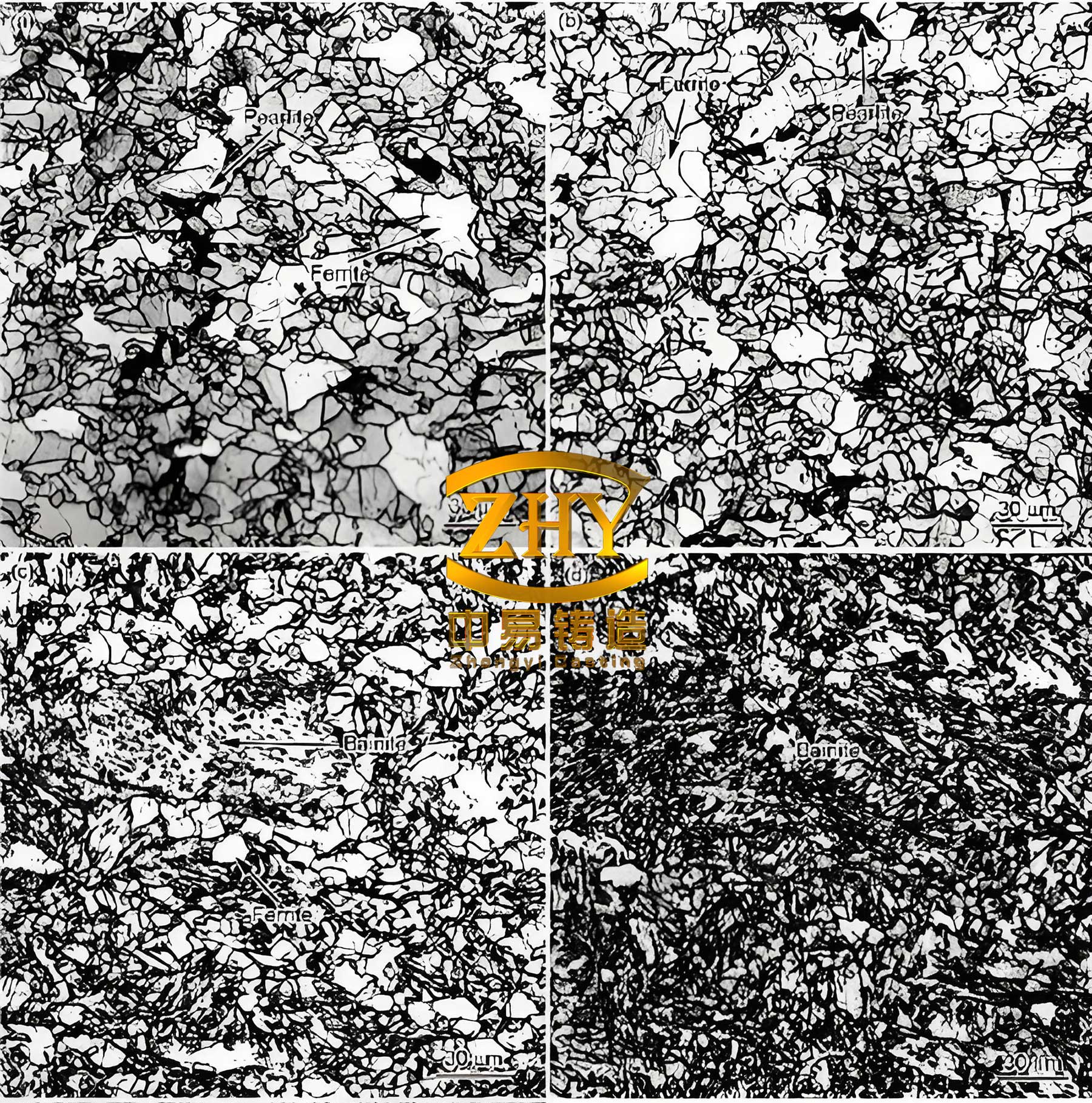
where k is thermal conductivity (≈40 W/m·K for spheroidal graphite cast iron), T is the peak temperature, and T_0 is ambient temperature. By controlling these factors, I ensure the weld zone of spheroidal graphite cast iron retains a ferritic-pearlitic matrix similar to the base metal. Another aspect is filler metal dilution, which influences weld composition. For spheroidal graphite cast iron repairs, the dilution ratio (D) should be minimized to prevent carbon pickup:
$$ D = \frac{A_{\text{BM}}}{A_{\text{WM}} + A_{\text{BM}}} $$
where A_BM is the area of melted base metal and A_WM is the area of weld metal. Keeping D below 30% helps maintain weld metal properties. These technical nuances underscore the complexity of welding spheroidal graphite cast iron and highlight the need for a methodical control flow.
In summary, this article has provided an in-depth exploration of the welding repair process control for spheroidal graphite cast iron end cap castings. From weldability analysis to practical parameter selection and qualification testing, each step is designed to address the unique challenges of spheroidal graphite cast iron. By adhering to this control flow, manufacturers can enhance the reliability and longevity of repaired components, ensuring they meet the rigorous demands of applications like railway engines. The frequent emphasis on ‘spheroidal graphite cast iron’ throughout this discussion reinforces its central role in this field, and the integration of tables and formulas offers a concise reference for practitioners. As technology evolves, continuous refinement of these processes will further optimize the welding of spheroidal graphite cast iron, contributing to sustainable manufacturing practices.