
The setting of simulation pretreatment mainly includes the selection of simulation items, material selection rules, heat exchange conditions, pouring conditions and general parameters. For the solidification simulation process of sand casting, the main setting process is as follows:
(1) Simulation project selection
In the simulation process of flat and ring sand castings, in order to compare the simulated temperature with the measured temperature, we only consider the simulation of solidification temperature field of sand castings without considering the pouring and filling process; The option selected in the simulation process is only the solidification cooling process, which can speed up the simulation rate and simplify the simulation process. After the completion of the simulation process, select the node temperature curve where the thermocouple is located.
(2) Material settings
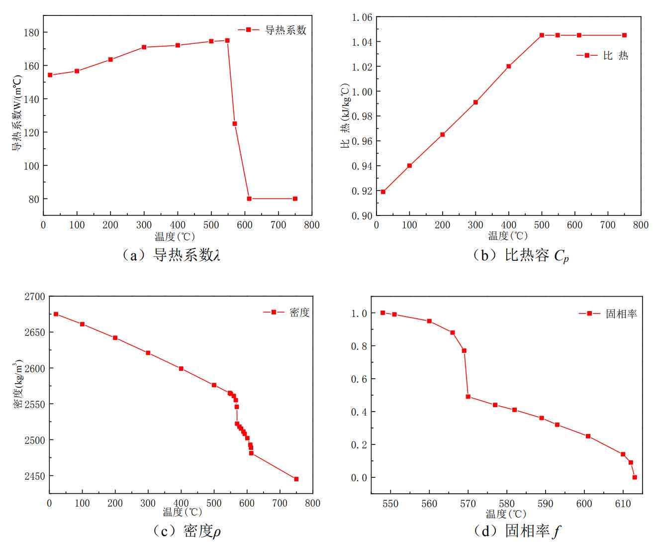
The selection of experimental materials for ring sand casting is: ZL101 Aluminum alloy material, furan resin sand is selected as the material of sand mold and sand core. Therefore, in the material setting, furan resin sand is selected as the sand core material of sand mold, ZL101 Aluminum alloy is selected as the sand casting material, and the initial filling rate is 100% assuming that the filling is completed immediately; The pouring temperature of molten metal is set at 705 ℃ and the mold temperature is 25 ℃. The thermophysical parameters of sand casting and sand mold (core) materials are manually defined in the user interface of visual cast to ensure that the simulated thermophysical parameters are the same as the actual ones as far as possible. The thermophysical parameters of sand mold (core) have been introduced in the experimental part of Chapter II. The thermophysical parameters of ZL101 are shown in Figure 1, Ensure that the simulation process conforms to the real situation and improve the simulation accuracy.
(3) Boundary heat transfer conditions
In the process of solidification and cooling of liquid metal, the heat transfer in the whole system includes: the interface heat transfer between sand casting and mold, the heat convection and heat radiation between mold and surrounding environment. The key part of this simulation is to select two different forms of interface heat transfer coefficient for comparison: the first is the simulation of the change of interface heat transfer coefficient with temperature, and the second is the simulation of constant interface heat transfer coefficient.
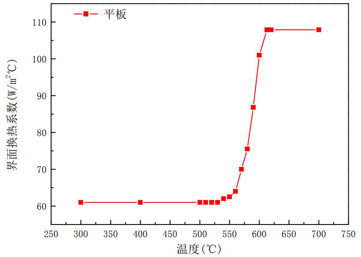
Add the temperature variation data of the internal and external interface heat transfer coefficient of flat sand casting and ring sand casting obtained by inverse calculation to the user interface customization. The data points defined by ProCAST cannot exceed 200. Select the interface heat transfer coefficient obtained by inverse calculation in sections, and connect the flat plate with sand mold, ring sand casting with inner sand core The heat transfer coefficient of the outer sand core interface is set as a curve with temperature. The data curve of heat transfer coefficient between sand mold and sand core of flat sand casting, ring sand casting and sand core added in ProCAST is shown in figures 2 and 3.
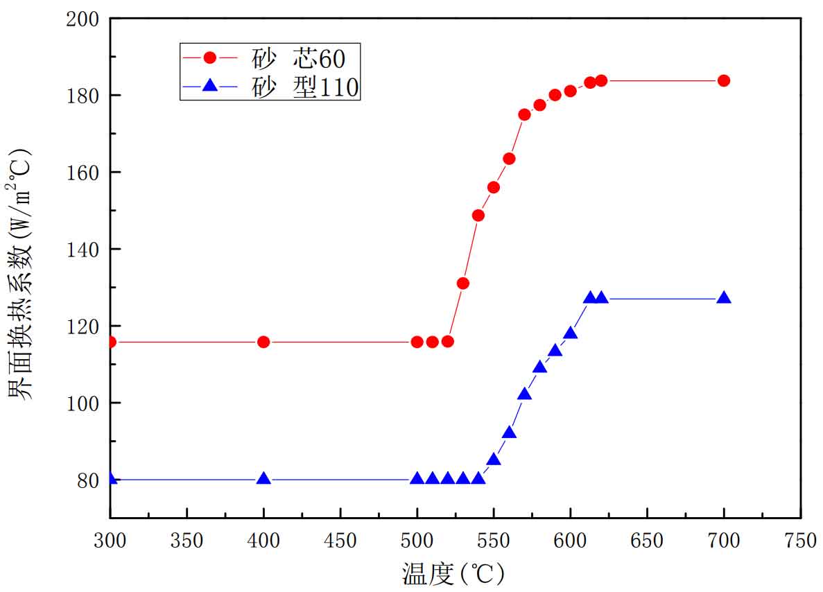
The interface heat transfer coefficient of ring sand casting shall be divided into three interfaces: the interface heat transfer coefficient calculated in Figure 3 shall be selected for the inner interface of ring / sand core and the outer surface of ring / sand mold, and the plate interface heat transfer coefficient calculated in Figure 2 shall be selected for the bottom of ring / sand mold interface. The interface with interface heat transfer coefficient to be added above is shown in Figure 4.
(4) Operating parameters
The operation parameters include the time step of simulation calculation, simulation termination temperature, simulation storage frequency, etc. In this experimental simulation, the calculation is terminated when the temperature of sand casting is lower than 300 ℃, and the actual simulation time is 1s. The calculated steps are twice (i.e. the time step is 0.5s, which is the same as the measured frequency). After the pre-processing setting of simulation is completed, click Run for simulation calculation, and analyze the simulation results through the post-processing interface visual viewer.