Compared with traditional sand casting process, lost foam casting technology has advantages such as precise casting size, good repeatability, flexible production, and good internal quality. The lost foam casting technology has developed rapidly worldwide. Nowadays, the lost foam casting technology is becoming mature both domestically and internationally, with a wide range of applications, especially suitable for complex shell parts. The application of lost foam casting technology in shell castings was analyzed in detail, and the main problems of current lost foam casting technology in the production of shell products were pointed out. Several casting defects, their causes, and corrective measures were emphasized. It is mainly manifested in that during the casting process of the mold cluster, with the foam gasification and accompanied by the flow and solidification of the liquid metal, there will be casting defects such as sand sticking, air holes, sand washing, etc. in the production of flywheel shell castings. Using flywheel shells and other products as examples, this article introduces the causes and improvement measures of defects related to lost foam casting.
Analysis of causes of sand adhesion in castings
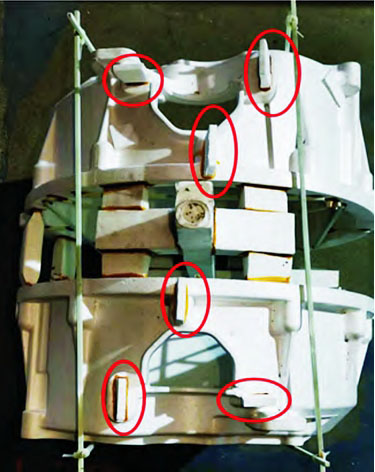
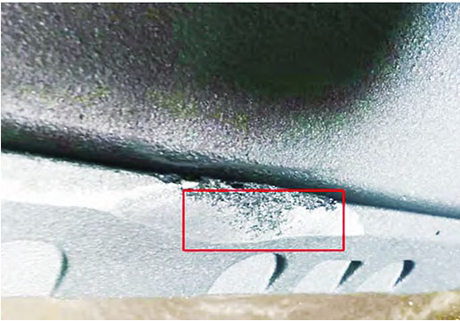
Sticky sand defect is a type of defect formed on the surface of castings during the pouring process when the molten metal and molding sand adhere to each other. Unreasonable placement, structural design, or process design of flywheel housing castings can result in mold clusters being unable to be compacted in the sand box, leading to sand sticking defects. The sticky sand on the flywheel shell is manifested as a mechanical mixture of sand particles and metal adhering to the surface of the shell. When cleaned, the surface has a metallic luster, which is a unique manifestation of mechanical sticky sand. Its main influencing factors are the compactness of the molding sand during molding, the fire resistance of the coating, the pouring temperature, and the coating thickness. Except for the sand sticking on the top of the casting, the rest of the flywheel housing is normal without any traces of sand sticking. Therefore, it is considered to be a problem with the compactness of the molding sand. The analysis shows that the reason is that ① the top of the flywheel housing cannot be filled with enough molding sand or the existing molding sand cannot be compacted; ② The gap between the two flywheel shells is too small, resulting in weak strength of the molding sand.
Based on the mechanism of sand adhesion in castings and its influencing factors, the following measures are mainly taken to solve it.
(1) According to the product structure, adjust the placement of the white mold, with the flywheel housing motor hole facing upwards to facilitate sand filling and ensure sufficient sand at the top of the flywheel housing.
(2) Increase the distance between the two flywheel shells from 80mm to 120mm, ensuring sufficient distance between the two mold clusters to ensure the compactness of the molding sand.
A root cause analysis was conducted on the issue of sand compaction in the flywheel housing, and two measures were taken to rectify the existing combination process, including product placement and combination spacing. During its normal production process, while ensuring that variables such as immersion coating process, pouring temperature, and vacuum pumping remained unchanged, production validation was carried out again from small to large batches, and no sand sticking defects were found. Through the above measures, the goal of completely solving the sand adhesion defect on the top of the flywheel housing has been achieved. When the molten iron enters the mold cluster, the white mold vaporizes and decomposes to generate a large amount of gas and residue, which cannot be discharged from the body in time, thus forming pores on the surface of the casting. The appearance of pores is related to pouring temperature, coating permeability, pouring speed, etc.
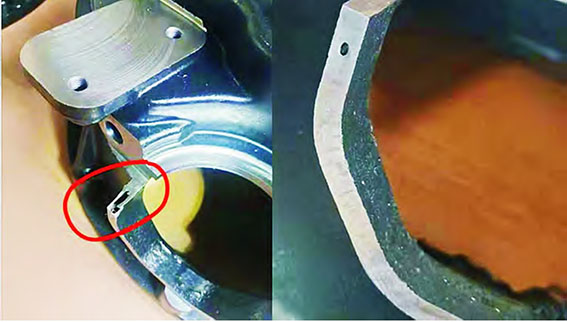
The porosity defect is manifested as normal appearance inspection on the surface or near the surface of the casting, but there are smooth pores of varying sizes on the surface after processing, and the pore walls also have oxidized color. The porosity is mainly concentrated at the top of the product, which is a unique manifestation of subcutaneous porosity. The main influencing factors are: ① In terms of pouring temperature, when the pouring temperature is low, the foam combustion is not sufficient, the gas is not completely discharged, and pores are formed under the skin; ② Local coating In terms of thickness, the motor hole coating is too thick, and the gas cannot be discharged after foam combustion, forming pores; ③ In terms of vacuum degree, the vacuum is too small, and the gas cannot be evacuated in time, forming pores; ④ Unreasonable process design, flying The top of the wheel housing lacks exhaust ports, and gas is concentrated at the top of the body and not completely discharged, forming air holes. Based on the mechanism of porosity in castings and its influencing factors, the following measures are mainly taken to solve it.
A root cause analysis was conducted on the issue of air holes in the flywheel housing, and four measures were taken to improve the existing process parameters, including product pouring temperature, coating thickness, pouring vacuum degree, and adding exhaust fins. During the process testing, the control variable method was adopted to ensure that the other three process parameters remained unchanged. Among them, Plan 1 increased the pouring temperature, produced and processed 20 pieces, 4 pieces of air holes, and the proportion of motor holes and air holes was 20%; Option 2 aims to reduce coating thickness by producing and processing 20 pieces, with 5 air holes, and motor holes accounting for 25% of the total air holes; Plan 3 aims to improve the vacuum degree by producing and processing 20 pieces, including 3 air holes. The proportion of air holes in the motor holes is 15%; Option 4 is to add exhaust fins, produce and process 20 pieces, 0 pieces of air holes, and the proportion of motor holes and air holes is 0%.
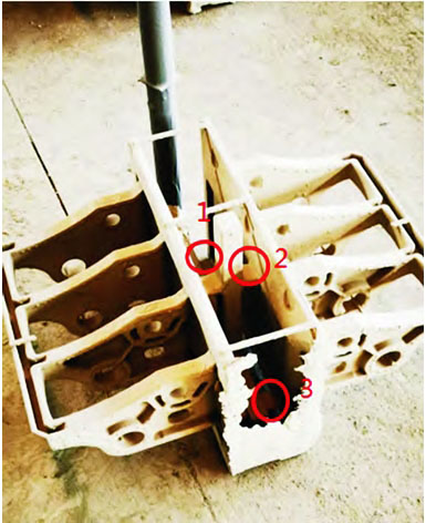
During the pouring process, the straight runner, transverse runner, and inner runner in the mold cluster pouring system are not completely sealed, especially the straight runner, which can easily form siphons and lead to sand flushing defects; The design of the product pouring system is unreasonable, the filling process is not smooth, the local pressure in the sprue is high, and the coating is broken due to the flushing of the iron liquid, which leads to the sand entering the mold cluster cavity with the iron liquid and also causes sand flushing defects [6]. Casting system for connecting rod frame castings. The product material is HT200, The mass is about 50kg, the contour dimensions are 572 mm × 380 mm × 348 mm, the bottom plate thickness is 12mm, and the existing process is to introduce molten iron into the side three-point inner runner, with inner runner dimensions of 60mm × 30mm × 6mm. The process parameters are as follows: the temperature of the molten iron is 1460-1470 ℃ (the melting equipment is an electric furnace), the pouring temperature is 1430-1440 ℃, the vacuum is -0.03MPa, there is no film coating or pressure holding, and the main defect is sand flushing. The location is concentrated in the bottom inner runner attachment, and the proportion of waste products is 20%.
The sand flushing defect is located at the bottom of the mold cavity in the straight line of the sprue and at the part of the mold cavity where the molten iron flows into the sprue. The nodular mixture of sand particles and metal that appears at this location is a unique manifestation of sand flushing. The main influencing factors are: ① low strength of the coating on the sprue, resulting in coating rupture due to molten iron flushing; ② The high pressure in the sprue caused the coating to crack; ③ During the pouring process, severe backflow of molten iron caused the coating to crack. However, during the pouring process of this product, the molten iron is poured smoothly without any backflow phenomenon, so the first two factors should be given special consideration. Based on the mechanism of sand flushing in castings and its influencing factors, the following measures are mainly taken to solve it.
(1) The current process involves dipping the coating twice with a thickness of 1.5mm, and adding another dipping process to the inner runner with a thickness of 2.2mm.
(2) Increase the number of internal runners and add an additional internal runner of the same size at the bottom two points. A root cause analysis was conducted on the sand flushing problem of the connecting rod frame, and the existing process parameters were analyzed, including the coating thickness and number of water inlets
Two measures were taken for rectification, and during the process of process testing, production validation was carried out from small to large batches while ensuring that the influencing parameters such as pouring temperature and vacuum degree remained unchanged.
Cleverly avoid casting defects through process design based on their causes. In the process of advancing process validation, the number of product advances is reduced from small to large, from small batches to large batches, in order to avoid significant losses caused by insufficient process considerations. In the process of process validation, we gradually advance step by step from five aspects: grasping the current situation, analyzing the reasons, formulating plans, implementing countermeasures, and confirming the effects, ultimately achieving the goal of thoroughly solving the problem.