
1. Introduction
In the operation of an engine, the main bearing seat endures diverse loads. The force from the combustion gas on the piston top is transmitted to the engine main bearing cover through the crank connecting rod mechanism. Meanwhile, due to the reciprocating and rotational motions of the crank connecting rod mechanism and crankshaft, the main bearing seat also bears the reciprocating inertia force and centrifugal force. The magnitudes and directions of these forces change with the working conditions and crankshaft angle, resulting in a complex stress state for the main bearing seat, which is subjected to various loads such as compression, bending, and torsion. The structural design of the main bearing seat must ensure sufficient strength and stiffness to handle these complex loads. Cracks and other forms of damage must be prevented, and deformation must be controlled within an acceptable range. In the design of the main bearing seat, the main bearing cover, as an essential part, its structural design and manufacturing process are crucial to the strength and stiffness of the entire engine main bearing seat, directly affecting the normal operation of the engine.
This article solves the problem of the fracture of the main bearing cover of a certain engine by optimizing its structural design and casting process. In the design process, special attention is paid to the material selection, structural strength analysis, and optimization of casting process parameters of the main bearing cover. Advanced engineering design software is used for structural simulation and strength analysis to ensure that the main bearing cover has sufficient strength and stiffness under various working conditions. At the same time, through the optimization of the casting process, the manufacturing quality and consistency of the main bearing cover are improved, and the risk of defects is reduced. Through the optimization of the structural design and manufacturing process of the main bearing cover, the problem of the fracture of the main bearing cover of a certain engine is successfully solved, ensuring the normal operation of the engine and improving the reliability and stability of the engine.
2. Experimental Background
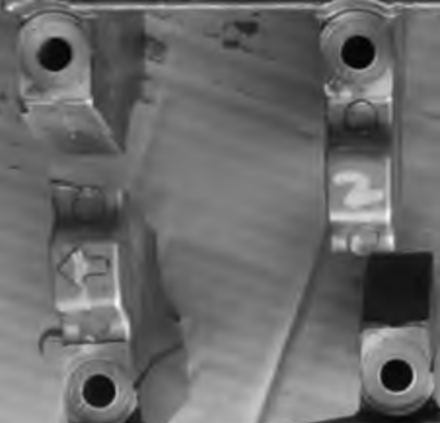
A 2.0T engine has an integral structure main bearing cover made of aluminum alloy and produced by high-pressure casting process. During the 800h cyclic load durability test of the engine, torque fluctuation occurred when it ran to 567h. Disassembly found that the 1st, 2nd, and 3rd gears of the main bearing cover were fractured, and the 4th and 5th gears had cracks.
3. Problem Analysis
3.1 Fracture Surface Analysis
The fracture initiation position is located on the side away from the crankshaft hole, near the thimble position used for demolding in the high-pressure casting process. Scanning electron microscopy analysis was performed on the fracture surface, and 200-times magnified scanning image of the fracture position. The analysis shows that the fracture type is cleavage brittle fracture, and no obvious fatigue striations are observed.
Metallographic analysis was performed on four sections at the fracture position . The metallographic pictures of sections 1# and 2# , and those of sections 3# and 4# .
The metallographic analysis results show that there are strip-like eutectic silicon and a small amount of blocky primary silicon on the white α solid solution matrix of sections 1# and 2#. This special structure not only affects the bonding between the eutectic silicon and the matrix but may also cause the eutectic silicon to cleave the matrix, thereby reducing the mechanical properties of the material in this region. In contrast, the eutectic silicon in samples 3# and 4# is round and elliptical, which is more conducive to improving the uniformity and overall performance of the material.
For the main bearing cover of the same batch of faulty parts, the tensile strength of the body was sampled and tested. The size of the sampling test piece, and the sampling position is 15mm above the crankshaft hole, as shown in the simplified diagram (i.e., at the horizontal line position). This position is selected based on the evaluation of the important parts of the engine main bearing cover to ensure the representativeness and reliability of the sampling. The tensile strength was measured to be 125MPa on the tensile testing machine (the tensile strength of the body sampling should be > 180MPa), which does not meet the requirements.
3.2 Crack Source Analysis
Through the structural analysis of the fracture position, it is found that the fracture source position is at the thimble position of the mold in the high-pressure casting process of the main bearing cover.
3.3 X-ray Analysis
X-ray analysis of the main bearing cover of the same batch of faulty parts found that there are severe gas and shrinkage holes and other casting defects in the body above the crankshaft hole, which can reduce the strength of the body.
The fracture is brittle, and the crack source is at the thimble position of the main bearing cover. There is strip-like eutectic silicon, resulting in poor mechanical properties. X-ray detection shows obvious gas and shrinkage holes above the crankshaft hole, with severe internal casting defects.
This engine main bearing cover is of aluminum alloy structure and produced by high-pressure casting process. After the aluminum liquid is filled, its state changes from liquid to solid, and phase change shrinkage inevitably occurs. The solidification characteristic of high-pressure casting parts is cooling from the outside to the inside. When the local position of the casting is thick, the cooling is slow, and shrinkage holes and porosity will inevitably occur inside. To ensure the strength of the main bearing cover, the wall thickness at each main shaft hole position is large, and gas and shrinkage holes are easily generated inside. If the casting process design is unreasonable, the internal casting defects will be aggravated.
In the die-casting process design of this main bearing cover, the thimble is arranged at the R corner, and there is residue at the thimble position in the actual product. The residue of the thimble affects the stress release at the R corner, resulting in stress concentration at the thimble position.
Comprehensive analysis shows that due to casting defects, the tensile strength of the body does not meet the requirements. Due to the unreasonable arrangement of the thimble position, stress concentration occurs, resulting in the generation of the crack source. Under high-speed and high-load working conditions, the strength does not meet the requirements, ultimately leading to fracture.
4. CAE Simulation Analysis
The strength and fatigue analysis of the main bearing seat of the faulty main bearing cover shows that the fatigue coefficient at the local position does not meet the requirements. Table 1 shows the simulation results of the stress and fatigue coefficient of the five gears. It is worth noting that the position with the minimum fatigue coefficient corresponds exactly to the fracture position. At this position, the fillet is subjected to the combined action of the bolt preload and the explosion pressure.
| Gear | Fatigue Safety Coefficient | Maximum Stress (MPa) | Standard |
|---|---|---|---|
| MB1 | 1.38 | 97.1 | OK |
| MB2 | 0.955 | 107.3 | Fatigue coefficient below the minimum limit of 1.1 |
| MB3 | 1.438 | 95.9 | OK |
| MB4 | 1.061 | 108.4 | Fatigue coefficient between the critical values of 1.0 – 1.1 |
| MB5 | 1.187 | 99.8 | OK |
If the design of the fillet is unreasonable or there are defects at the fillet position, initial cracks will be generated at the fillet position. Under the action of alternating loads, the cracks will expand, ultimately leading to the fracture of the main bearing cover. Therefore, for such positions, especially in the design stage, detailed analysis and consideration are required to ensure that the fillet design is reasonable and there are no defects. This can effectively prevent the fracture of the main bearing cover and improve the reliability and safety of the product.
5. Structural and Process Optimization
5.1 Structural Optimization
The structure above the main bearing hole is changed by removing the protrusion, reducing the wall thickness, and canceling the sinking R corner.
The optimized structure is simulated and calculated by CAE under the same simulation boundary and using the same method. The calculation results are shown in Table 2, and all gears meet the requirements.
| Gear | Fatigue Safety Coefficient | Maximum Stress (MPa) | Standard |
|---|---|---|---|
| MB1 | 2.06 | 67.1 | OK |
| MB2 | 1.336 | 78.73 | OK |
| MB3 | 2.172 | 65.4 | OK |
| MB4 | 1.535 | 72.5 | OK |
| MB5 | 1.771 | 63.5 | OK |
5.2 Process Optimization
A series of improvement measures are taken to address the internal casting defects in the locally thick positions. First, the casting pressure is increased to ensure full filling inside the casting. At the same time, the mold temperature is controlled to improve the overall quality of the casting. For the thick positions, the high-pressure spot cooling casting process is added to enhance the local cooling effect and help reduce the occurrence of defects. In addition, the casting runner is thickened to improve the internal flow and further reduce the possibility of defects.
To further improve the quality and performance of the product, the thimble is moved to the non-force-bearing position of the part to reduce the impact of the thimble on the local area of the part. After the structural and process optimization, the tensile strength of the main bearing cover is tested. The actual measurement results show that the tensile strength is basically greater than 150MPa, indicating that the optimized product has high strength.
To verify the durability of the product, an engine durability test is conducted. After 3000 cold and hot shocks and 800 hours of cyclic load test, the main bearing cover shows no fracture phenomenon, indicating that the product has good stability and reliability under actual use conditions. These improvement measures effectively solve the internal casting defect problem in the locally thick positions and improve the quality and performance of the product.
6. Conclusion
- In the design process of the engine main bearing cover, attention should be paid to the position with the maximum force to avoid stress concentration and perform optimization design.
- In the production process of the main bearing cover, the process plan should pay attention to the stress concentration position, especially the casting thimble arrangement must avoid being arranged at the position with the maximum force.
- The casting process should pay attention to the locally thick positions and adopt processes such as high-pressure spot cooling and local extrusion to improve internal defects.
- The quality of the sample parts should be controlled. Real-time confirmation of the casting quality can be achieved through means such as X-ray detection, sectioning, and tensile strength testing of the body.