
In my extensive experience as a foundry engineer specializing in advanced casting techniques, the lost foam casting process has proven to be a transformative method for manufacturing critical components like impellers and guide casings for submersible pumps. These parts, with their complex spatial curved surfaces and thin-walled geometries, directly influence hydraulic performance and operational reliability. Traditional sand casting methods often struggle with these complexities, requiring multiple cores, which lead to shape deviations, high surface roughness, and increased machining allowances. The lost foam casting process eliminates cores, parting lines, and mold assembly, enabling near-net-shape production with superior surface finish and dimensional accuracy. This article delves into the intricacies of applying the lost foam casting process to these thin-walled parts, covering material selection, pattern making, coating, molding, pouring, and defect analysis, all from a first-person perspective based on practical implementation.
The heart of the lost foam casting process lies in the creation of high-quality foam patterns. For submersible pump impellers and guide casings, the patterns must replicate intricate, twisted blade profiles with wall thicknesses as low as 3 mm. I have found that material choice is paramount. Typically, the castings are made from HT200 or QT450-10, but the foam patterns require specific expandable polystyrene (EPS) or expandable polymethyl methacrylate (EPMMA) beads. For the delicate blades, I prefer using fine-grade EPS beads, such as domestic TZ-01 or imported Afcolene, with a post-pre-expansion density ($\rho_{pre}$) controlled within the range of 0.025–0.030 g/cm³. This “heavy” density aids in complete mold filling and smooth surface formation. For other less critical sections, medium-fine beads with a density of 0.020–0.025 g/cm³ suffice. The guiding principle is to minimize density without compromising成型 integrity and surface roughness, as lower density reduces gas generation during pouring. The pre-expansion process can be described by the following relationship, which I often use to optimize parameters:
$$ \rho_{pre} = \frac{m_{initial}}{V_{expanded}} = f(P_{steam}, T_{steam}, t_{expansion}) $$
where $P_{steam}$ is the steam pressure, $T_{steam}$ is the temperature, and $t_{expansion}$ is the expansion time. After pre-expansion, the beads must be aged to allow surface moisture evaporation and stabilisation of the blowing agent. Inadequate aging leads to poor成型, while excessive aging causes blowing agent loss.
| Component Part | Bead Type | Target Pre-expansion Density (g/cm³) | Key Considerations |
|---|---|---|---|
| Impeller Blades, Guide Vane Blades | Fine EPS (e.g., TZ-01) | 0.025–0.030 | Ensures complete filling of thin sections; provides smooth surface. |
| Impeller Shroud, Guide Casing Body | Medium-fine EPS/EPMMA | 0.020–0.025 | Balances structural integrity and gas generation reduction. |
The成型 of these complex patterns is perhaps the most critical step in ensuring final casting quality. The impeller pattern typically consists of blades and a front shroud glued together, while the guide casing comprises blades, an outer shell, and an end block. To achieve flawless thin-blade成型, I employ a pressure-assisted injection method. Key factors include the density and size of mold vent holes, cleanliness of the mold cavity, design of the feed inlet and injection gun, and gas pressure. The following parameters have yielded consistent results in my work:
- Steam Pressure for成型: 0.10–0.15 MPa (maintained stable).
- Heating Time: Component-dependent, typically 20–40 seconds. Overheating causes blade scorching; underheating leads to poor fusion and surface quality.
- Cooling Time: Sufficient to allow pattern solidification and easy demolding, usually 2–3 times the heating time. Insufficient cooling causes sticking and pattern damage.
After demolding, patterns must be dried to remove residual moisture. I use a combination of natural air drying and controlled oven drying. The oven temperature is maintained between 40–50°C, with drying times exceeding 24 hours. Rapid drying at high temperatures must be avoided to prevent pattern distortion. The dried patterns are then assembled using jigs and glued, with the gating system attached. A perfect pattern is the absolute cornerstone of a successful lost foam casting process.
Once the pattern cluster is ready, it must be coated with a refractory layer. The coating serves multiple vital functions in the lost foam casting process: it prevents metal penetration (avoiding burns-on and sand sticking), enhances pattern rigidity to resist distortion during sand filling, facilitates the evacuation of pattern decomposition gases, and improves casting surface finish for easier shakeout. From my practice, the coating must exhibit:
- High permeability to allow rapid gas escape.
- Good wettability and adhesion to form a uniform, adequate-thickness layer.
- High refractoriness and low thermal expansion.
- Fast drying characteristics.
For thin-walled impellers and casings, I apply the coating in 2–3 layers, ensuring no bare spots. Each layer must be completely dried before applying the next. The final coating thickness is crucial and can be related to the pattern geometry and metal head pressure. A simplified model I use for coating thickness ($t_c$) estimation is:
$$ t_c \geq \frac{P_{metal} \cdot d_{feature}}{2 \cdot \sigma_{coating}} $$
where $P_{metal}$ is the metallostatic pressure, $d_{feature}$ is a characteristic dimension (e.g., blade thickness), and $\sigma_{coating}$ is the coating’s green strength. The coating slurry’s properties, like viscosity and solids content, are tightly controlled. The permeability ($K$), a critical parameter, can be expressed as a function of coating structure:
$$ K \propto \frac{\phi^3}{ (1-\phi)^2 \cdot S^2 \cdot \tau^2 } $$
where $\phi$ is porosity, $S$ is specific surface area of the refractory particles, and $\tau$ is tortuosity. Achieving the right balance is key; a coating that is too permeable may not prevent metal penetration, while one that is too dense hinders gas evolution.
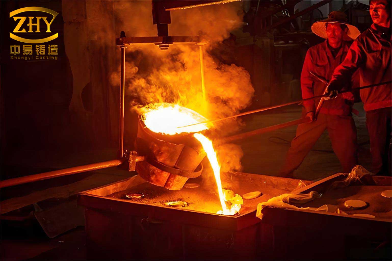
The image above illustrates a typical setup in the lost foam casting process, showing the pattern cluster coated and ready for molding. This visual representation underscores the integration of pattern assembly and coating within the overall workflow.
Molding involves filling the flask with dry, unbonded silica sand and compacting it around the pattern cluster. I use a dedicated vibration table for this purpose. The process begins by placing a base layer of sand (at least 100 mm thick) in the flask, leveling it, and then carefully positioning the pattern cluster. Sand is then added via a rain-shower system to ensure uniform filling without causing pattern displacement. The pattern should be at least 100 mm away from the flask walls. Compaction is done in multiple stages to achieve a high and uniform sand density around the complex blade geometries. Insufficient compaction leads to loose sand that can cause mold wall movement and casting defects like swelling or sand inclusions. Over-compaction risks pattern deformation. The goal is a sand compactness that supports the pattern without altering its shape. The vibration parameters—frequency ($f$), amplitude ($A$), and time ($t_{vibe}$)—are optimized empirically. A useful relationship for the compaction energy ($E_c$) per unit volume is:
$$ E_c \approx \int_{0}^{t_{vibe}} A^2 \cdot f^3 \, dt $$
After compaction, a plastic film is placed over the flask top to create a seal for the subsequent vacuum application. The sprue cup is positioned, and more sand is added to cover the film, preventing it from burning through during pouring.
The application of vacuum is a defining feature of the lost foam casting process. Before pouring, a vacuum of 0.04–0.06 MPa is applied to the flask. This negative pressure serves to stabilize the mold, remove pattern decomposition gases through the coating, and enhance metal fluidity. Precise control is essential. In my operations, I maintain the vacuum within this range throughout pouring and for a short period afterward. If the vacuum is too low (<0.04 MPa), defects like wrinkles, carbonaceous deposits, sand sticking, increased carbon pickup, porosity, misruns, and cold shuts can occur. If it is too high (>0.06 MPa), defects such as white spots (unpyrolyzed foam inclusions), pinholes, nodules, and penetration become likely. The gas evacuation rate ($\dot{Q}_{gas}$) can be modeled as:
$$ \dot{Q}_{gas} = \frac{K \cdot A \cdot \Delta P}{\mu \cdot L} $$
where $K$ is the coating permeability, $A$ is the area, $\Delta P$ is the pressure difference (vacuum level), $\mu$ is the gas viscosity, and $L$ is the effective travel path length.
| Parameter | Recommended Range for Thin-Walled Pump Parts | Consequences of Deviation | Underlying Principle |
|---|---|---|---|
| Pouring Temperature | 30–50°C above sand casting norms; typically 1420–1480°C for iron. | Too Low: Wrinkles, cold shuts. Too High: Penetration, burn-on, excessive carbon pickup. | Must provide sufficient heat to vaporize foam rapidly and maintain metal fluidity in thin sections. |
| Pouring Speed | Start with a thin, steady stream; increase to a larger stream; finish with a thin stream at the riser. | Too Fast: Sprayback, turbulence, gas entrapment, slag. Too Slow/Sporadic: Misruns, cold shuts, wrinkles, carbon accumulation. | Metal front advancement should match foam degradation rate to maintain a stable interface. |
| Metal Composition (Cast Iron) | Carbon equivalent at lower specification limit; minimize free carbon. | High Carbon Equivalent: Increased carbon pickup from foam, promoting carburization and carbon defects. | Reduces the thermodynamic driving force for carbon absorption from decomposing foam. |
| Vacuum Level | 0.04–0.06 MPa (stabilized during pour) | As detailed in the text above. | Balances mold stability, gas removal, and metal flow dynamics. |
Pouring is the moment of truth in the lost foam casting process. The metal must replace the foam pattern smoothly and completely. For our thin-walled components, I have established that pouring temperature needs to be significantly higher than in conventional sand casting—by 30–50°C, or even more, aiming for an optimal range. This compensates for the heat absorbed by the endothermic foam decomposition process. The pouring sequence is critical: begin with a small, controlled stream to initiate gradual foam degradation without violent gas generation (which causes sprayback), then increase the flow rate to maintain a consistent metal front, and finally, top up the riser with a smaller stream to ensure proper feeding. The ideal condition is where the metal fill velocity ($v_{metal}$) equals the foam pyrolysis front velocity ($v_{foam}$):
$$ v_{metal} \approx v_{foam} = \frac{\dot{m}_{decomp}}{\rho_{foam} \cdot A_{interface}} $$
where $\dot{m}_{decomp}$ is the mass decomposition rate of the foam, $\rho_{foam}$ is its density, and $A_{interface}$ is the area of the metal-foam interface. The chemical composition of the iron is also tailored. I specify melt charges to the lower limit of the standard chemical composition, particularly for carbon equivalent (CE), to minimize the amount of free carbon available, thereby reducing the tendency for carbon pickup from the decomposing foam.
Despite meticulous control, defects can arise. Based on my analysis of production runs for pump impellers and guide casings, the most common issues are cold shuts and carbonaceous wrinkles (folded, tar-like deposits). Let’s analyze these in detail, incorporating first-hand observations.
Cold Shuts: These appear as lines or seams on the casting surface where two metal streams fail to fuse completely. Causes I’ve identified include: 1) Metal temperature drop due to heat absorption by foam decomposition, especially severe in thin blades. 2) Improper gating design leading to premature cooling or turbulent flow. 3) Excessively high vacuum causing metal to rush along the mold walls, forming a thin shell that later-incoming metal cannot remelt. Preventive measures I implement are: increasing pouring temperature by an additional 20-30°C if necessary; redesigning gating to top-pour via a hollow sprue to shorten flow length and reduce heat loss; and carefully modulating vacuum levels.
Carbonaceous Wrinkles and Carbon Pickup: These manifest as black, glossy, folded surfaces or localized hard spots with high carbon content. They occur primarily on outer surfaces of guide casings and blade edges. The root cause is the incomplete expulsion of liquid pyrolysis products from the decomposing foam. Contributing factors from my experience are: 1) Inadequate pouring temperature or poor gating, failing to fully gasify the foam. 2) Coating with insufficient permeability or poor wetting characteristics, trapping liquid residues. 3) Excessive sand compaction or low vacuum, hindering gas and liquid evacuation. The prevention strategy involves a multi-pronged approach: optimizing the lost foam casting process parameters as per Table 2; developing coatings with high hot-strength and tailored permeability to allow liquid pyrolysis products to wick away; and ensuring proper sand compaction and vacuum application.
| Defect Type | Primary Causes (Based on Observation) | Corrective Measures (Implemented First-Person) | Related Process Variable |
|---|---|---|---|
| Cold Shuts / Misruns | Low pouring temp; slow/inconsistent pouring; high vacuum causing wall rush; long flow length. | Increase pouring temp 20-50°C; use top-pour hollow sprue; moderate vacuum (0.045-0.055 MPa); ensure steady, rapid pour after initial fill. | $T_{pour}$, $v_{pour}$, $\Delta P_{vac}$, gating design. |
| Carbon Wrinkles / Folds | Incomplete foam degradation; coating with low permeability/ hot-strength; low vacuum; high foam density. | Increase $T_{pour}$; optimize coating recipe for permeability & adhesion; maintain vacuum at 0.05 MPa; use lower density foam where possible. | $T_{pour}$, Coating $K$, $\Delta P_{vac}$, $\rho_{foam}$. |
| Surface Carbon Inclusions (Black Spots) | Entrapment of foam decomposition liquids/solids; localized coating failure. | Enhance coating drainage property; ensure uniform coating coverage; increase vacuum slightly to aid removal. | Coating properties, $\Delta P_{vac}$. |
| Dimensional Distortion | Pattern deformation during drying/sand filling; uneven sand compaction. | Control drying temperature (<50°C); use staged, gentle vibration; employ supportive fixturing for delicate patterns. | $T_{dry}$, Vibration parameters, pattern support. |
| Sand Inclusions / Penetration | Coating cracks or insufficient thickness; high metal static pressure; low coating refractoriness. | Increase coating layers/thickness; apply seal coat; reduce pouring height if possible; use higher refractoriness coatings. | $t_c$, Coating chemistry, $P_{metal}$. |
The mathematical modeling of foam decomposition is central to understanding and mitigating these defects. The rate of foam mass loss can be approximated by an Arrhenius-type equation:
$$ \frac{dm}{dt} = -A_0 \cdot e^{-\frac{E_a}{R T_{interface}}} \cdot (m)^{n} $$
where $A_0$ is a pre-exponential factor, $E_a$ is the activation energy for pyrolysis, $R$ is the gas constant, $T_{interface}$ is the temperature at the metal-foam interface, and $n$ is the reaction order. Controlling the interface temperature through pouring parameters is therefore critical.
In conclusion, the successful application of the lost foam casting process to thin-walled, complex submersible pump impellers and guide casings demands a holistic and tightly controlled approach. From my firsthand involvement, every step—from selecting the correct foam bead density and mastering pattern成型 to formulating the perfect coating recipe, executing precise sand compaction and vacuum control, and finally managing the pouring thermodynamics—is interlinked. The lost foam casting process is not merely a sequence of steps but a system where parameters interact dynamically. The advantages, however, are substantial: elimination of cores, significant reduction in machining allowance, improved surface finish leading to enhanced hydraulic efficiency, and a better working environment. The key to consistency lies in treating the process as an integrated system, continuously monitoring and adjusting variables based on a deep understanding of the underlying physics and chemistry, as outlined in the formulas and tables presented. Future work in my practice involves further refining these models and exploring advanced coating materials to push the limits of thin-section casting via the lost foam casting process.