
In the hydrometallurgy industry, impurity pumps are critical for transporting solid-liquid slurries, which often contain high concentrations of chloride ions, a pH range of 1–2, and 20%–35% hard abrasive particles. The impeller, as the core component, faces severe acid corrosion, particularly chloride-induced pitting, along with abrasive wear, erosion, and contact fatigue wear. This accelerates failure, leading to increased costs and resource wastage. Historically, markets have been dominated by foreign manufacturers with limited technical disclosure and short service lives of 3–4 months. To address this, I embarked on developing a novel FeCr40 ultra-high chromium material and an advanced lost foam casting process to produce high-quality impellers with extended lifespan, exceeding 5–7 months in service, thereby breaking international monopolies and enabling large-scale supply.
The development focused on two main aspects: first, the research and preparation of FeCr40 material with optimized composition and microstructure for enhanced acid-corrosion resistance and wear resistance; second, the design of a lost foam casting process integrating large-mouth outflow and balanced solidification theories, validated through virtual simulation. This approach not only improved domestic manufacturing capabilities but also facilitated the application of new materials in harsh environments. Below, I detail the systematic study, incorporating tables and formulas to summarize key findings.
Development of FeCr40 Ultra-High Chromium Material
The material must meet specific performance and microstructural requirements to withstand wet metallurgy conditions. Based on the Fe-C-Cr ternary system phase diagram, the equilibrium solidification involves liquidus reactions leading to the formation of carbides and matrix phases. For FeCr40, the composition was tailored to achieve a dual-phase matrix of ferrite and austenite with dispersed carbides, ensuring a balance of toughness, strength, and resistance.
Performance Requirements: The material requires excellent acid corrosion resistance, especially against chloride pitting; high hardness to resist abrasive wear; sufficient strength for rotational stresses; and good impact toughness to prevent cracking. These were achieved through compositional optimization.
Microstructural Requirements: According to the Fe-C-Cr ternary liquidus projection, at point U1 (1275°C), a peritectic-eutectic transformation occurs: $$L + \delta-Fe \rightleftharpoons M_{23}C_6 + \gamma-Fe$$. For FeCr40, with low carbon and high chromium, M23C6 carbides form, providing high wear resistance. The carbide volume fraction (CVF) can be estimated using Mardey’s relation:
$$CVF (\%) = 12.33 \times \omega(C) + 0.55 \times \omega(Cr) – 15.2$$
where $\omega(C)$ and $\omega(Cr)$ are weight percentages. With optimized composition, CVF reaches 30%–35%. The eutectic carbon content is given by:
$$Eutectic\ C (\%) = 4.4 – 0.054 \times \omega(Cr)$$
For FeCr40, this ranges from 2.3% to 2.8%, classifying it as hypoeutectic high-chromium iron. The final microstructure comprises fine ferrite-austenite duplex matrix with isolated, dispersed carbides, as shown in microstructural analysis.
Compositional Optimization: Using JMatPro Cast software, phase diagrams were analyzed to adjust elements, resulting in the composition in Table 1. Key influences include:
– Carbon: Forms carbides; higher content increases hardness but must balance brittleness. Range: 1.7%–3.2%.
– Chromium: Enhances corrosion resistance via passivation and raises electrode potential; part forms hard (Fe,Cr)23C6 carbides (HV 1000–1100). High Cr/C ratio promotes ferritic matrix. Range: 33%–45%.
– Molybdenum: Solid-solution strengthens matrix, improves high-temperature stability. Range: 0.5%–3%.
– Nickel: Stabilizes austenite, improves toughness and corrosion resistance. Range: 3.0%–6.0%.
– Copper: Increases electrode potential and chloride resistance. Range: 1.0%–3.5%.
| Element | Range | Role |
|---|---|---|
| C | 1.7–3.2 | Carbide formation, hardness |
| Cr | 33–45 | Corrosion resistance, carbide formation |
| Mo | 0.5–3.0 | Matrix strengthening, high-temperature stability |
| Ni | 3.0–6.0 | Austenite stabilization, toughness |
| Cu | 1.0–3.5 | Electrode potential improvement, chloride resistance |
Comprehensive Evaluation: FeCr40 offers a unique microstructure with suitable strength, high wear-corrosion resistance, and good impact toughness. However, its casting properties are poor: low fluidity due to hypoeutectic composition, wide solidification range causing shrinkage, brittleness from high carbide content, and tendency for slag and gas defects. These challenges were addressed through the lost foam casting process design.
Lost Foam Casting Process Design for Impeller
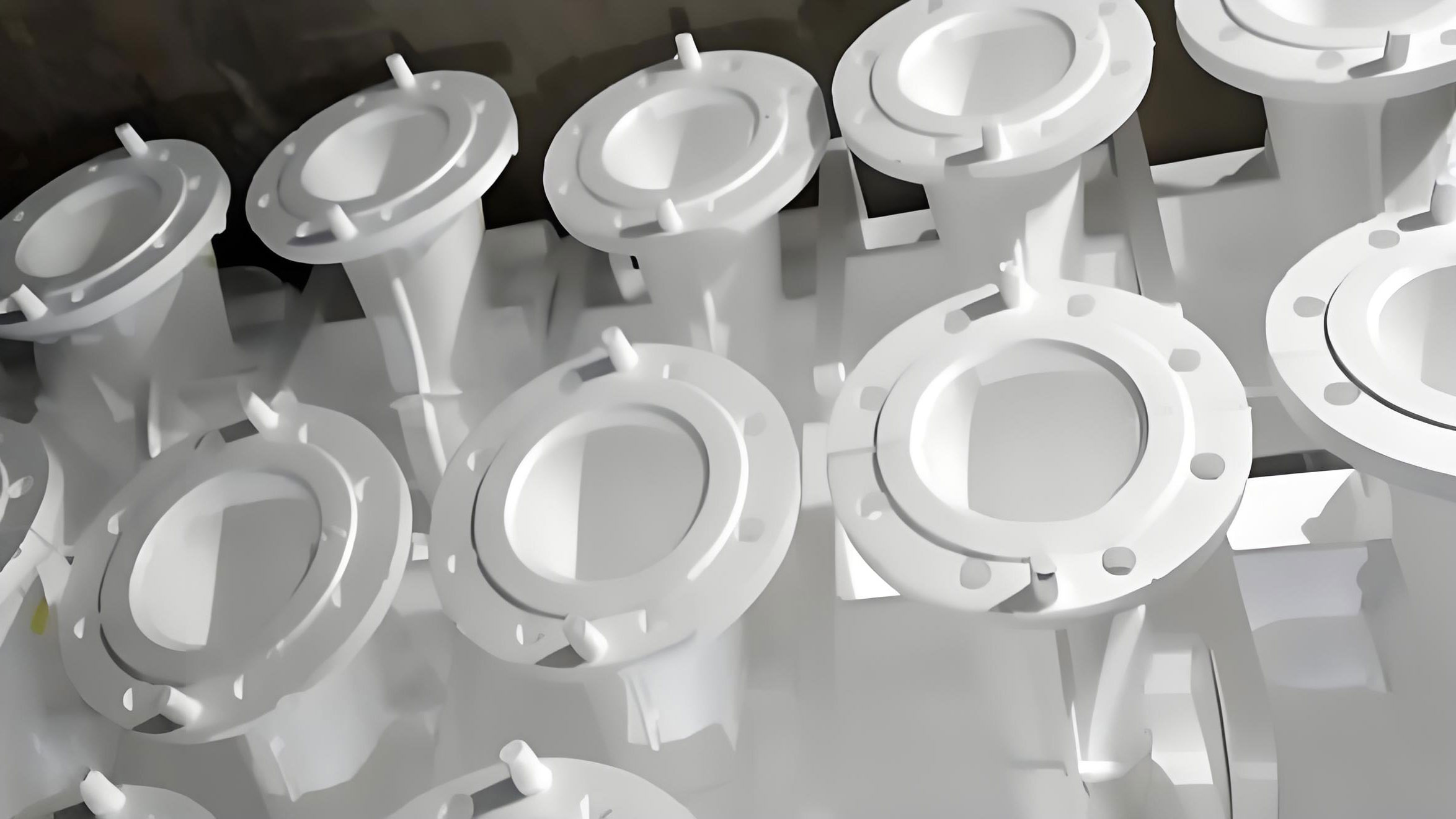
The lost foam casting process was employed to manufacture the impeller, utilizing a horizontal molding and vertical pouring approach. Key strategies included a bottom-gating large-mouth outflow system, balanced solidification risers, pre-embedded sleeves for grain refinement, and virtual simulation for optimization. The process schematic illustrates the arrangement, but here I focus on design principles.
Gating System Design: Based on large-mouth outflow theory, a bottom-gating, closed, multi-channel, dispersed system was used to ensure steady filling and rapid mold filling. In lost foam casting, metal front replacement with foam absorbs heat and hinders flow, exacerbated by the material’s poor fluidity. To counter this, the gating system was enlarged (1.3–2.5 times traditional sand casting), with two wide and thick runners并联 on a longitudinal sprue, and convex structures at runner ends to trap inclusions. Ingates were placed at blade and cover plate junctions, equipped with ceramic filters for slag removal and flow stabilization. This design promotes bottom-up filling, disperses thermal stress, and reduces cracking risk. The mathematical basis for flow rate can be expressed as:
$$Q = A \cdot v$$
where $Q$ is flow rate, $A$ is cross-sectional area, and $v$ is velocity. Enlarging $A$ ensures rapid filling within 20 seconds, as confirmed by simulation.
Riser Design: Following balanced solidification theory, risers were designed to prevent shrinkage and cracks. The impeller has hot spots at hub roots and blade-cover plate junctions. While large risers aid feeding, they may induce stress in brittle materials. Thus, multiple dispersed risers were used to balance feeding and stress. Quantitative design parameters are summarized in Table 2.
| Riser Type | Neck Size (× Hot Spot) | Diameter (× Hot Spot) | Height (× Diameter) | Function |
|---|---|---|---|---|
| Lower risers (2) | 1.05–1.25 | 3.5–5.0 | 1.2–1.5 | Feed hub hot spots, blades, inlet edges |
| Upper risers (2) | 1.05–1.15 | 1.3–1.5 | 1.1–1.3 | Venting, top feeding, reduce wall effect defects |
Five blades correspond to five thermal channels (two linked to gates, three to risers), ensuring even thermal distribution and solidification. Riser removal via hammering was done carefully to avoid震裂.
Pre-embedded Sleeve Design: A quenched 45# steel sleeve was embedded in the hub bore to act as an internal chill, refining grains, enhancing strength, and facilitating thread machining. The sleeve design includes ring bands with planar edges and grooves to prevent axial and radial movement. It also aids directional solidification. The cooling effect can be modeled using Fourier’s law:
$$q = -k \frac{dT}{dx}$$
where $q$ is heat flux, $k$ is thermal conductivity, and $\frac{dT}{dx}$ is temperature gradient. The sleeve increases $q$, accelerating solidification at the bore.
Virtual Simulation of Casting Process: Simulation using JMatPro Cast and CASTSoft software optimized process parameters. First, JMatPro Cast calculated thermophysical properties for FeCr40, such as liquidus temperature (1360°C), derived from liquid fraction vs. temperature plot (Figure 1). Data like density, viscosity, thermal conductivity, and specific heat were imported into CASTSoft for filling and solidification analysis.
$$Liquid\ Fraction\ vs.\ Temperature:\ f_L(T) = \int_{T_{solidus}}^{T_{liquidus}} \frac{dL}{dT} dT$$
For FeCr40, pouring temperature was set at 1440 ± 10°C considering mold filling and heat absorption.
Simulation steps included pre-processing (defining materials, boundary conditions) and post-processing (outputting filling and solidification results). Filling simulation showed steady flow with layer flow, taking 20 seconds, confirming gating design. Solidification simulation revealed temperature fields, cooling rates, and shrinkage. Initially, slight shrinkage occurred at top risers; after optimizing riser size (increasing modulus), defects were eliminated, achieving balanced solidification. The solidification time was 4320 seconds. Key outputs are summarized in Table 3.
| Simulation Phase | Key Outputs | Results | Optimization |
|---|---|---|---|
| Filling | Flow temperature field, velocity field, pressure field | Steady filling, 20 s, layer flow | None needed |
| Solidification | Temperature field, cooling rate, solid-liquid fraction, shrinkage | Initial shrinkage at top risers | Increased riser modulus, eliminated shrinkage |
The successful simulation validated the lost foam casting process, ensuring defect-free impellers.
Application and推广 of FeCr40 Material in Impurity Pumps
Starting with the Φ500 impeller, the FeCr40 material and lost foam casting process were extended to 29 flow-pass components across eight pump sizes (Φ100 to Φ1000), including casings and guard plates. This enabled bulk supply of complete pumps, capturing market share and demonstrating technical leadership. The economic impact has been significant, with annual sales exceeding substantial figures, and it has fostered international collaboration.
The lost foam casting process proved crucial for achieving high-quality castings, leveraging its advantages such as reduced machining, complex shape capability, and minimal sand usage. Key formula summaries include:
– Carbide volume fraction: $$CVF = 12.33\omega(C) + 0.55\omega(Cr) – 15.2$$
– Eutectic carbon content: $$C_{eutectic} = 4.4 – 0.054\omega(Cr)$$
– Heat transfer in pre-embedded sleeve: $$q = k \frac{\Delta T}{L}$$
where $\Delta T$ is temperature difference and $L$ is thickness.
In conclusion, the development of FeCr40 material and optimized lost foam casting process has enabled production of high-performance impellers for acid-corrosion and wear-resistant applications. The integration of material science and advanced casting techniques, validated through simulation, represents a breakthrough in impurity pump manufacturing. Future work may focus on further alloy modifications and process refinements to enhance performance in even harsher environments.