
In modern industrial applications, the production of durable and efficient casting molds is critical for processes such as iron casting in blast furnace operations. Among various casting techniques, lost foam casting has emerged as a prominent method due to its ability to produce complex shapes with high precision and minimal defects. This study focuses on the application of lost foam casting for manufacturing iron molds, leveraging numerical simulation tools to optimize the process and investigating the microstructural and mechanical properties of the resulting castings. Through this research, we aim to provide insights into how lost foam casting can be enhanced to produce molds with improved performance and longevity.
The lost foam casting process involves using a foam pattern that vaporizes upon contact with molten metal, leaving behind a precise cavity that forms the cast part. This method eliminates the need for cores and reduces post-casting machining, making it cost-effective for medium to large-scale production. For iron molds, which are subjected to cyclic thermal stresses during service, the integrity of the casting is paramount to prevent failures such as cracking or deformation. Here, we delve into the intricacies of lost foam casting, from material selection to process simulation, and evaluate the material’s response to thermal exposure.
Material choice plays a pivotal role in determining the performance of cast iron molds. Typically, cast iron or cast steel is used, but for lost foam casting, we selected a ZG30Cr steel composition due to its favorable balance of strength and thermal resistance. The chemical composition of ZG30Cr is summarized in Table 1, which highlights key elements that influence microstructural development.
| Element | Content (wt.%) |
|---|---|
| C | 0.24–0.35 |
| Mn | 0.5–0.8 |
| Cr | 0.8–1.2 |
| Si | 0.2–0.5 |
| S/P | ≤0.4 |
| Fe | Balance |
This composition promotes the formation of acicular ferrite and pearlite upon solidification, which contributes to enhanced toughness and crack resistance. In lost foam casting, the material’s behavior during solidification is critical, and numerical simulation helps predict potential defects. We employed the ViewCast software to model the lost foam casting process, setting parameters such as pouring temperature at 1650°C, sand mold initial temperature at 25°C, and a negative pressure of -400 kPa to facilitate mold filling and reduce gas entrapment.
The design of the gating system in lost foam casting is essential for ensuring smooth metal flow and effective feeding. Based on hydraulic calculations, the cross-sectional areas of the gating components were determined. For instance, the total cross-sectional area of the ingates can be estimated using the formula:
$$ \sum S_{\text{in}} = \frac{G}{\mu t \sqrt{0.31 H_p}} $$
where \( G \) is the mass of metal flowing through the ingates (in kg), \( \mu \) is the flow coefficient (0.4–0.6 for cast iron), \( t \) is the pouring time (in s), and \( H_p \) is the pressure head height (in cm). For our iron mold, with dimensions of 792 mm × 334 mm × 190 mm, we designed ingates of 30 mm × 40 mm, runners of 40 mm × 40 mm, and a sprue of 40 mm × 40 mm. Additionally, a top riser was incorporated to compensate for solidification shrinkage, with its volume calculated as:
$$ \epsilon (V_{\text{riser}} + V_{\text{casting}}) \leq V_{\text{riser}} \cdot \eta $$
where \( \epsilon \) is the volumetric shrinkage rate (1.6% for this steel) and \( \eta \) is the riser efficiency (11%). This yielded a riser volume of approximately \( 2.2 \times 10^3 \, \text{cm}^3 \), designed as a rectangular block of 100 mm × 100 mm × 218 mm. The use of insulating risers in lost foam casting can further enhance feeding by increasing the thermal modulus by a factor of 1.3–1.4, as described by the relation:
$$ M_{\text{insulated}} = k \cdot M_{\text{standard}} $$
with \( k \approx 1.3 \) for non-cylindrical geometries. Such design considerations are vital for achieving directional solidification and minimizing defects in lost foam casting.
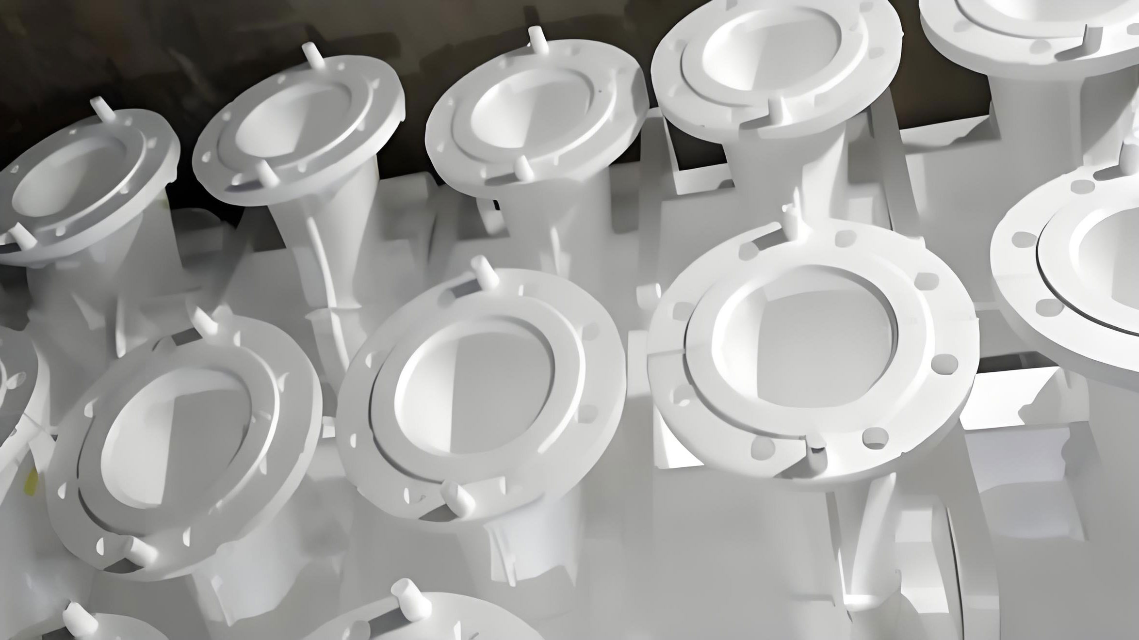
To visualize the lost foam casting process, a schematic representation is often helpful. Below, we include an image that illustrates the typical setup and flow of molten metal in a lost foam casting system, highlighting the vaporization of the foam pattern and the formation of the casting.
Numerical simulation using ViewCast allowed us to predict the filling and solidification sequences in the lost foam casting process. The software solves the governing equations for fluid flow and heat transfer, including the energy equation:
$$ \rho C_p \frac{\partial T}{\partial t} = \nabla \cdot (k \nabla T) + Q $$
where \( \rho \) is density, \( C_p \) is specific heat, \( T \) is temperature, \( t \) is time, \( k \) is thermal conductivity, and \( Q \) represents heat sources such as latent heat release. For our simulation, the mesh consisted of approximately 2 million elements to capture detailed thermal gradients. The filling process showed that metal entered the gating system at 0.3 s, reached the lower parts of the mold by 1.0 s, and completely filled the cavity by 7.18 s, with the riser filled thereafter. This orderly filling is crucial in lost foam casting to avoid turbulence and defect formation.
Solidification analysis revealed that directional solidification was achieved, starting from the mold extremities and progressing inward. The solidification time \( \tau \) can be estimated using Chvorinov’s rule:
$$ \tau = \left( \frac{M}{K} \right)^2 $$
where \( M \) is the modulus (volume-to-surface area ratio) and \( K \) is the solidification coefficient. For the iron mold, the modulus varied across sections, but the riser design ensured that \( M_{\text{riser}} > M_{\text{casting}} \), promoting adequate feeding. The simulation predicted minimal shrinkage porosity, primarily confined to the central upper region of the casting, which is acceptable for service conditions. This outcome underscores the efficacy of lost foam casting in producing sound castings when coupled with numerical optimization.
Following the simulation, we produced actual castings using the lost foam casting process and conducted microstructural and mechanical evaluations. The as-cast microstructure of ZG30Cr steel, observed under optical microscopy, consisted predominantly of acicular ferrite and pearlite, forming a Widmanstätten structure. This structure arises from rapid cooling in hypo-eutectoid steels and can impact mechanical properties. The hardness of the material was measured using Rockwell hardness tests, with results summarized in Table 2 for different heat treatment conditions simulating service environments.
| Condition | Temperature (°C) | Hardness (HRC) |
|---|---|---|
| As-cast | – | 28.5 |
| Heated | 500 | 28.0 |
| Heated | 700 | 27.8 |
| Heated | 900 | 22.3 |
The data indicates that heating to 500°C and 700°C caused negligible changes in hardness, consistent with the microstructural stability of ferrite and pearlite at these temperatures. However, at 900°C, a significant drop in hardness occurred due to phase transformations. During heating, ferrite and pearlite transform to austenite, and upon cooling, a finer distribution of pearlite and ferrite forms, as described by the Avrami equation for transformation kinetics:
$$ f = 1 – \exp(-k t^n) $$
where \( f \) is the transformed fraction, \( k \) is a rate constant, and \( n \) is the Avrami exponent. This refinement leads to reduced hardness but improved toughness, which is beneficial for thermal fatigue resistance in lost foam casting molds.
Oxidation tests were also performed to assess the high-temperature behavior of the material. The oxidation rate \( r \) can be expressed as:
$$ r = \frac{\Delta m}{A \cdot t} $$
where \( \Delta m \) is the mass change, \( A \) is the surface area, and \( t \) is time. We found that temperature profoundly influenced oxidation rates, with thicker oxide films forming at higher temperatures, thereby altering diffusion kinetics. For instance, at 900°C, the formation of Fe₂O₃ and Cr₂O₃ scales provided some protection, but overall oxidation accelerated compared to lower temperatures. This insight is crucial for designing lost foam casting molds that operate under cyclic thermal loads.
The integration of numerical simulation with experimental validation highlights the robustness of lost foam casting for producing iron molds. By optimizing gating and riser designs through tools like ViewCast, we can mitigate defects such as shrinkage cavities and porosity. Moreover, the microstructural analysis reveals that ZG30Cr steel develops a favorable mix of ferrite and pearlite, which can be tailored via heat treatment to enhance service life. In industrial contexts, lost foam casting offers advantages like reduced machining and higher dimensional accuracy, making it a preferred choice for mold manufacturing.
To further elucidate the process parameters, we can consider the effects of varying negative pressure in lost foam casting. The pressure differential \( \Delta P \) aids in removing decomposition products from the foam pattern, and its optimal value can be derived from fluid dynamics principles. For a porous medium like sand, the Darcy equation applies:
$$ v = -\frac{\kappa}{\mu} \nabla P $$
where \( v \) is the velocity, \( \kappa \) is permeability, \( \mu \) is viscosity, and \( \nabla P \) is the pressure gradient. In our simulation, a negative pressure of -400 kPa was used, which proved effective in ensuring complete filling and minimal gas defects. This parameter is critical in lost foam casting and should be adjusted based on pattern density and metal type.
Another aspect is the cooling rate during solidification, which influences microstructure formation. The cooling rate \( \dot{T} \) can be approximated from thermal simulation data and correlated with secondary dendrite arm spacing (SDAS) using the relation:
$$ \lambda_2 = a \dot{T}^{-b} $$
where \( \lambda_2 \) is SDAS, and \( a \) and \( b \) are material constants. For ZG30Cr steel, a faster cooling rate typical of lost foam casting due to the insulating effect of the foam pattern can lead to finer microstructures, thereby improving mechanical properties. This underscores the importance of controlling process variables in lost foam casting to achieve desired outcomes.
In summary, lost foam casting is a versatile and efficient method for producing iron molds, and numerical simulation serves as a powerful tool for process optimization. Our study demonstrates that through careful design and analysis, lost foam casting can yield castings with minimal defects and tailored microstructures. Future work could explore advanced materials or hybrid techniques to further enhance the capabilities of lost foam casting in industrial applications. The repeated emphasis on lost foam casting throughout this discussion highlights its significance in modern manufacturing, and ongoing research will continue to refine its implementation for challenging environments.
From a broader perspective, the principles of lost foam casting can be extended to other alloys and geometries, leveraging simulation to reduce trial-and-error. The use of computational fluid dynamics (CFD) coupled with heat transfer models allows for precise prediction of metal flow and solidification patterns. For example, the continuity and momentum equations for incompressible flow in lost foam casting can be written as:
$$ \nabla \cdot \mathbf{v} = 0 $$
$$ \rho \left( \frac{\partial \mathbf{v}}{\partial t} + \mathbf{v} \cdot \nabla \mathbf{v} \right) = -\nabla p + \mu \nabla^2 \mathbf{v} + \mathbf{f} $$
where \( \mathbf{v} \) is velocity, \( p \) is pressure, and \( \mathbf{f} \) represents body forces. Solving these equations numerically enables the identification of potential issues like cold shuts or misruns in lost foam casting processes.
Additionally, the economic benefits of lost foam casting are substantial, as it reduces material waste and labor costs compared to traditional sand casting. By eliminating cores and minimizing post-casting operations, lost foam casting enhances productivity, especially for medium to high-volume production. This aligns with sustainable manufacturing goals, making lost foam casting an attractive option for industries seeking efficiency and precision.
In conclusion, the integration of numerical simulation and microstructural analysis in lost foam casting for iron molds provides a comprehensive framework for quality assurance and performance enhancement. The insights gained from this research can guide practitioners in optimizing lost foam casting parameters, ultimately leading to more durable and reliable castings. As technology advances, lost foam casting will likely see increased adoption, driven by its ability to meet the demanding requirements of modern engineering applications.