
In our foundry practice, the adoption and refinement of lost foam casting has been a transformative journey, particularly for producing large, complex castings with stringent quality requirements. Lost foam casting, also known as expendable pattern casting, involves using a foam pattern that vaporizes upon contact with molten metal, leaving behind a precise cavity. This process offers significant advantages in reducing machining allowances, minimizing core assembly, and enhancing dimensional accuracy. However, as with any casting method, challenges such as shrinkage porosity, gas defects, and economic viability must be addressed through meticulous process optimization. In this article, I will delve into our experiences and systematic improvements in lost foam casting, focusing on工艺 adjustments that have drastically reduced defect rates and elevated production efficiency for heavy-duty components like machine tool beds and industrial wear parts. Throughout this discussion, the term lost foam casting will be emphasized to underscore its centrality in our methodology.
The foundational principle of lost foam casting relies on the decomposition of a foam pattern—typically made of expandable polystyrene (EPS)—within a unbonded sand mold. When molten metal is poured, the foam vaporizes, and the metal fills the cavity exactly. This eliminates the need for traditional cores in many cases, simplifying mold assembly. However, the process is sensitive to parameters such as pattern density, coating integrity, gating design, and pouring temperature. In our initial trials for large castings, we encountered persistent issues: shrinkage cavities at feeder necks, gas porosity from pattern decomposition gases, and prolonged cleaning times. These defects, often exceeding 20–30% scrap rates, threatened the scalability of lost foam casting for high-volume production. Thus, we embarked on a comprehensive reevaluation of our lost foam casting工艺, integrating empirical data with theoretical models to forge a robust framework.
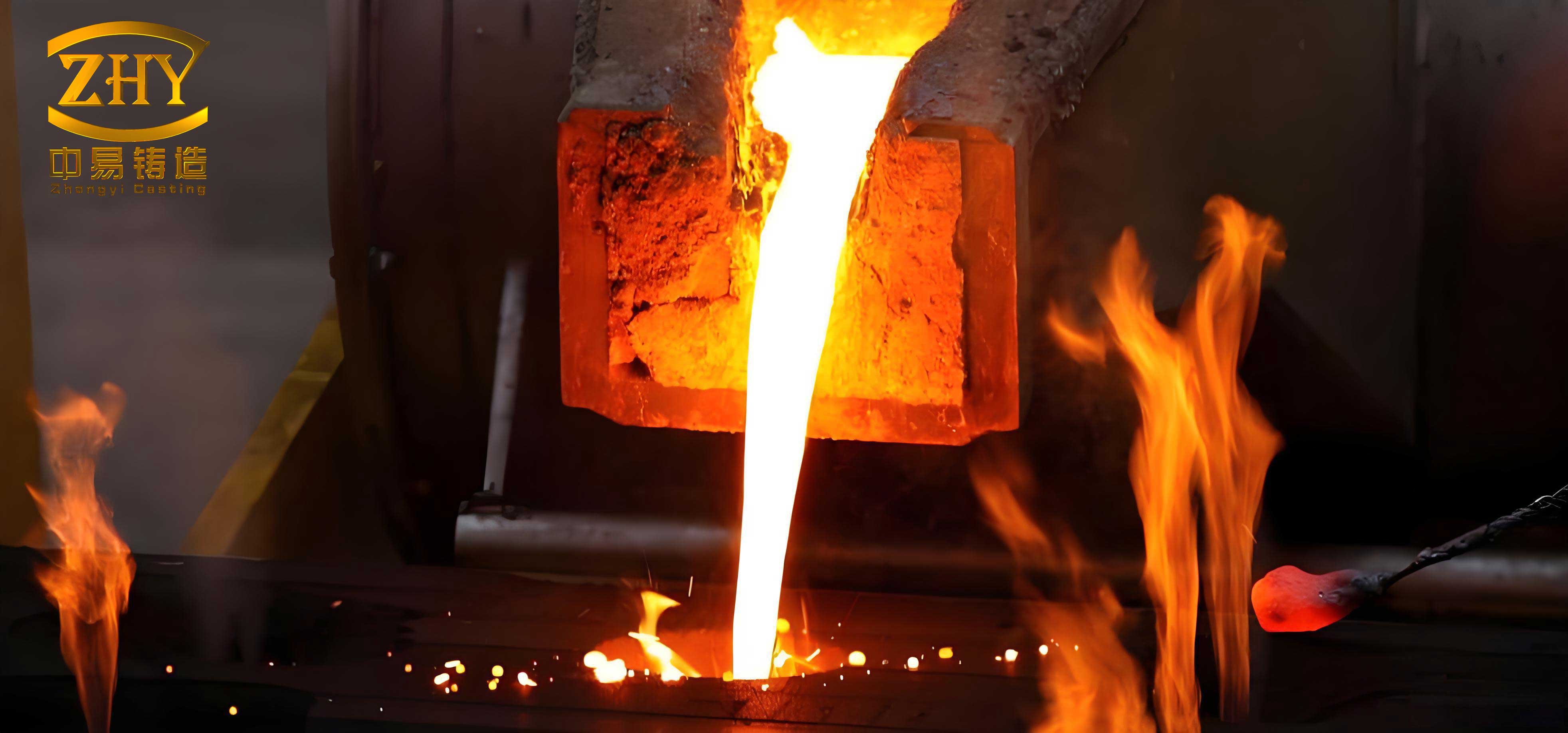
To quantify the challenges, we analyzed the defect mechanisms in lost foam casting. Shrinkage porosity primarily stems from inadequate feeding during solidification, especially in thick sections like feeder roots. Gas defects arise from incomplete evacuation of pyrolysis products from the foam pattern, which can become trapped in the metal. The gating system in lost foam casting plays a dual role: it must facilitate rapid filling to minimize foam gas generation while ensuring thermal gradients conducive to directional solidification. Our original gating design for a rear liner plate (approximate weight: 1.5 tons) utilized a single sprue with multiple ingates and four large insulating feeders. This layout, though conventional, led to turbulent flow and gas entrapment. The resin sand mold, while providing good strength, contributed to gas evolution due to moisture absorption and binder decomposition. We modeled the heat transfer and fluid dynamics using simplified equations to guide our redesign. For instance, the solidification time \( t_s \) in a sand mold can be approximated by Chvorinov’s rule:
$$ t_s = k \left( \frac{V}{A} \right)^2 $$
where \( V \) is volume, \( A \) is surface area, and \( k \) is a mold constant specific to lost foam casting conditions. By optimizing the feeding distance and feeder placement, we aimed to reduce \( t_s \) in critical zones.
The revamped lost foam casting工艺 incorporated several key modifications, each targeting specific defect sources. First, we redesigned the gating system to promote laminar flow and enhance gas evacuation. Instead of a central sprue, we implemented multiple ingates around the component periphery, coupled with an overflow channel and vent holes. The gating ratio was recalibrated to an open system:
$$ \sum F_{\text{sprue}} : \sum F_{\text{runner}} : \sum F_{\text{ingate}} = 1.0 : 1.5 : 4.0 $$
This ratio ensures progressive filling and minimizes velocity-related turbulence. For the rear liner, six ingates of Ø40 mm were positioned along the outer edge, with a Ø40 mm overflow opposite the sprue and a Ø50 mm vent at the geometric center. Additionally, we reduced the number of feeders from four to one large Ø260 mm insulating feeder, placed atop the casting to exploit thermal gradients. This adjustment significantly improved the yield, as calculated by:
$$ \text{Yield} = \frac{\text{Casting Weight}}{\text{Total Metal Poured}} \times 100\% $$
Our target was to increase yield from 62% to over 70%, thereby reducing molten metal consumption and energy costs in lost foam casting.
Second, we addressed mold-related gas generation in lost foam casting. The resin sand molds, though advantageous for complex shapes, can absorb moisture and release volatiles during pouring. To mitigate this, we introduced a pre-heating protocol: molds were dried at 200°C for one hour using electric hot-air blowers prior to pouring. This step reduced the sand’s moisture content and binder reactivity, lowering the gas evolution rate. Moreover, we tilted the mold assembly by 5–8° during clamping to facilitate natural gas escape through the vents and upper surface. The tilting angle \( \theta \) was chosen based on empirical trials to balance gas venting and metal flow stability. The gas pressure \( P_g \) in the mold cavity can be estimated by:
$$ P_g = \frac{nRT}{V} – \rho g h \sin \theta $$
where \( n \) is moles of gas, \( R \) is the gas constant, \( T \) is temperature, \( V \) is cavity volume, \( \rho \) is metal density, \( g \) is gravity, and \( h \) is metal head height. By tilting, we effectively reduced \( P_g \) and minimized gas entrapment.
Third, we tightened control over melting and pouring practices in lost foam casting. Charge materials were limited to virgin alloys where possible; when using returns, we mandated shot blasting to remove oxides and sand residues. This reduced the inclusion content and gas-forming impurities. The molten iron was superheated to 1450°C, then held in the ladle for 2–3 minutes to allow slag separation and temperature homogenization. Pouring temperature was strictly controlled between 1370°C and 1390°C, favoring the lower end to decrease the foam decomposition rate. The relationship between pouring temperature \( T_p \) and gas generation rate \( G \) in lost foam casting can be expressed as:
$$ G = A e^{-E_a/(RT_p)} $$
where \( A \) is a pre-exponential factor, \( E_a \) is activation energy for foam decomposition, and \( R \) is the universal gas constant. Lower \( T_p \) reduces \( G \), thereby diminishing gas defects. We also employed fast pouring to shorten the mold-metal contact time, further limiting gas evolution.
The impact of these changes was dramatic, as summarized in Table 1, which compares the original and optimized lost foam casting工艺 for the rear liner plate. The data underscore the holistic benefits of our approach, from defect reduction to labor savings.
| Parameter | Original Lost Foam Casting工艺 | Optimized Lost Foam Casting工艺 | Improvement |
|---|---|---|---|
| Molding Time (minutes) | 40–50 | 25–35 | ~30% reduction |
| Shrinkage/Gas Defect Rate | ~30% | ~2% | 93% reduction |
| Process Yield | 62% | 70% | 8 percentage points increase |
| Cleaning and Grinding Time (hours) | 6 | 2 | 67% reduction |
Beyond defect control, lost foam casting proved exceptionally advantageous for single-piece or small-batch large castings, such as machine tool columns. We produced a立柱 (column) measuring 7800 mm × 1800 mm × 2600 mm, with a weight of 36 tons and material specification HT300 (grey iron with tensile strength ≥300 MPa). The traditional approach—core assembly molding—would have incurred high pattern costs and extended lead times. Instead, we employed lost foam casting with a EPS pattern machined from foam boards. The pattern design incorporated draft angles instead of fillets to simplify machining, and critical sections like guide rails (100 mm thick) were oriented downward to promote sound solidification. The gating system was multi-tiered: five levels of ingates using ceramic tubes for the sprue and runner, with the ratio set at 1.0:1.5:4.0. This ensured uniform filling across the massive volume. The mold was made in a large flask (9000 mm × 2500 mm) with reduced binder content (10–15% less than conventional sand casting) to enhance sand flowability around the pattern. After coating with a graphite-based slurry (Baumé density 60–70) and drying at 50–60°C for 24 hours, the pattern was embedded and compacted. Pouring was conducted at 1380–1400°C with rapid filling to minimize foam residue.
The results validated the efficacy of lost foam casting for such mammoth components. Surface finish surpassed that of wood pattern castings, with minimal flashing except at vent holes. Dimensional distortion was limited to approximately 5 mm on side faces, acceptable for machining allowances. Mechanical properties exceeded specifications: tensile strength of 315 MPa and hardness of 210 HB. The economic analysis revealed even more compelling advantages. Pattern costs for lost foam casting were 90% lower than for solid wood patterns and 70% lower than for core assembly patterns. Additionally, the near-net-shape capability of lost foam casting reduced grinding labor by 70–80%, as evidenced by the cleaning time data. The overall cost per ton of casting dropped significantly, making lost foam casting a viable option for low-volume heavy sections.
To generalize our findings, we developed a set of guidelines for optimizing lost foam casting processes. These can be encapsulated in formulas and checklists. For instance, the optimal pouring temperature range \( T_{\text{opt}} \) for grey iron in lost foam casting can be derived from the balance between fluidity and gas generation:
$$ T_{\text{opt}} = T_{\text{liquidus}} + \Delta T_{\text{superheat}} – \Delta T_{\text{safety}} $$
where \( T_{\text{liquidus}} \) is the alloy’s liquidus temperature (≈1150°C for HT300), \( \Delta T_{\text{superheat}} \) is typically 150–200°C for adequate fluidity, and \( \Delta T_{\text{safety}} \) is a reduction of 20–30°C to curb foam gas. Thus, \( T_{\text{opt}} \) falls around 1370–1390°C, as we implemented. Similarly, the feeder sizing in lost foam casting must account for the exothermic decomposition of foam; we use the modulus method adjusted by a foam factor \( f_f \):
$$ M_f = f_f \cdot M_c $$
where \( M_f \) is the feeder modulus, \( M_c \) is the casting modulus, and \( f_f \) ≈ 1.2–1.5 for lost foam casting due to the additional heat from foam vaporization.
Another critical aspect is the coating technology in lost foam casting. The coating serves as a barrier to prevent sand erosion and facilitate gas permeability. We formulated a water-based graphite coating with viscosity tailored to pattern complexity. The coating thickness \( \delta_c \) influences both strength and gas transit; we aim for:
$$ \delta_c = \frac{k_c \cdot \sqrt[3]{V_p}}{A_p} $$
where \( V_p \) is pattern volume, \( A_p \) is pattern surface area, and \( k_c \) is an empirical constant (≈0.1–0.2 mm for large castings). Proper drying is essential to achieve a compressive strength >1 MPa, as measured by penetrometer tests.
Table 2 summarizes the key parameters and their recommended values for successful lost foam casting of large components, based on our cumulative experience. This table serves as a quick reference for practitioners aiming to replicate our results.
| Parameter | Symbol | Recommended Range | Remarks |
|---|---|---|---|
| Pattern Density | ρ_p | 20–25 kg/m³ | EPS foam, lower density reduces gas but may compromise strength |
| Coating Baumé Density | B | 60–70 | For water-based graphite coatings; ensures adequate coverage |
| Drying Temperature | T_d | 50–60°C | For 24 hours to remove moisture without pattern distortion |
| Gating Ratio (Sprue:Runner:Ingate) | ∑F_s : ∑F_r : ∑F_i | 1.0 : 1.5 : 4.0 | Open system to minimize turbulence in lost foam casting |
| Pouring Temperature (Grey Iron) | T_p | 1370–1390°C | Lower end preferred to reduce gas evolution |
| Mold Tilt Angle | θ | 5–8° | Facilitates gas escape; adjust based on geometry |
| Feeder Modulus Factor | f_f | 1.2–1.5 | Multiplier for Chvorinov’s rule in lost foam casting |
| Sand Binder Reduction | ΔB | 10–15% | Compared to conventional resin sand; enhances compaction |
The economic implications of adopting lost foam casting extend beyond direct cost savings. By slashing pattern expenses and post-casting labor, the break-even point for small batches lowers considerably. We can model the total cost \( C_{\text{total}} \) for a casting lot as:
$$ C_{\text{total}} = C_{\text{pattern}} + C_{\text{molding}} + C_{\text{melting}} + C_{\text{finishing}} $$
In lost foam casting, \( C_{\text{pattern}} \) is dramatically reduced due to foam’s low cost and machinability. For our machine column, \( C_{\text{pattern}} \) was less than 10% of a wooden pattern’s cost. \( C_{\text{finishing}} \) also drops because lost foam casting yields smoother surfaces with minimal fins. Assuming a production volume \( N \) castings, the average cost per unit \( \bar{C} \) becomes:
$$ \bar{C} = \frac{C_{\text{fixed}}}{N} + C_{\text{variable}} $$
where \( C_{\text{fixed}} \) includes pattern and tooling, and \( C_{\text{variable}} \) covers material and labor. Lost foam casting reduces both terms for low \( N \), making it ideal for prototypes or custom heavy equipment.
Looking forward, we are exploring further refinements in lost foam casting. One area is the use of advanced foam materials, such as polymethylmethacrylate (PMMA), which decomposes more cleanly than EPS, potentially reducing gas defects. We are also integrating simulation software to predict foam degradation and metal flow, using equations like the energy balance during decomposition:
$$ \frac{dm_f}{dt} = -k_f A_f (T – T_v) $$
where \( m_f \) is foam mass, \( k_f \) is decomposition rate constant, \( A_f \) is surface area, \( T \) is local metal temperature, and \( T_v \) is vaporization temperature. Coupled with computational fluid dynamics, this allows us to optimize gating and venting before physical trials, saving time and resources.
In conclusion, lost foam casting has proven to be a versatile and economical process for large-scale castings when meticulously engineered. Our journey from high defect rates to consistent quality underscores the importance of holistic工艺 control—from pattern making to pouring. By redesigning gating, pre-treating molds, and fine-tuning melting parameters, we have harnessed the full potential of lost foam casting. The data tabulated herein and the formulas derived offer a roadmap for others seeking to implement or improve lost foam casting in their foundries. As we continue to innovate, lost foam casting will undoubtedly remain a cornerstone of our manufacturing strategy for complex, heavy components, driving efficiency and competitiveness in the global market.