
As a casting engineer specializing in advanced foundry techniques, I have extensively worked with the lost foam casting process, particularly in the production of high-precision machine tool castings. This process, pioneered by H.F. Shroger in the 1950s, has revolutionized the manufacturing of complex components, such as machine tool columns and uprights, due to its ability to achieve tight dimensional tolerances and intricate geometries. However, in my experience, the lost foam method is not without challenges. Defects like skin penetration, collapse, and iron nodules frequently arise, especially in large-scale machine tool castings, leading to significant scrap rates. In this article, I will delve into these issues, analyze their root causes using theoretical models and empirical data, and present optimized solutions that have proven effective in my practice. The focus will remain on machine tool casting applications, emphasizing how process refinements can yield superior cast components for industrial machinery.
The lost foam process involves creating a foam pattern, coating it with a refractory material, embedding it in unbonded sand, and then pouring molten metal while applying a vacuum. The foam vaporizes upon contact with the metal, and the resulting gases are evacuated through the sand, allowing the metal to fill the mold cavity. For machine tool castings, such as dual-wall columns or uprights, this process is ideal due to the need for precise dimensions and complex internal structures. However, the very factors that make it advantageous—such as the use of unbonded sand and reliance on negative pressure—also introduce vulnerabilities. In my work, I have encountered numerous cases where machine tool castings, weighing between 500 kg and 2000 kg, exhibited defects that compromised their integrity. Through systematic investigation, I have identified key parameters that must be controlled to ensure quality.
One common defect in machine tool casting via lost foam is skin penetration, where sections of the casting fail to form properly, resulting in missing material. This often occurs in areas with large internal cavities and restricted venting paths. During pouring, the rapid vaporization of foam generates substantial gases. If these gases cannot be quickly evacuated, the local negative pressure drops, reducing the sand’s rigidity. The molten metal’s buoyancy then causes sand displacement, leading to mold failure. To quantify this, the gas generation rate can be modeled using the ideal gas law and heat transfer equations. For instance, the volume of gas produced from foam decomposition can be estimated as:
$$ V_g = \frac{m_f \cdot R \cdot T}{P \cdot M} $$
where \( V_g \) is the gas volume, \( m_f \) is the mass of foam, \( R \) is the universal gas constant, \( T \) is the temperature, \( P \) is the pressure, and \( M \) is the molar mass of the foam. In machine tool casting applications, this gas must be swiftly removed to maintain a stable mold. Another defect is collapse, where the top section of the casting lacks material due to insufficient sand support. This is typically caused by inadequate sand compaction or low negative pressure, allowing the metal’s buoyant force to disrupt the sand matrix. The buoyancy force \( F_b \) can be expressed as:
$$ F_b = \rho_m \cdot g \cdot V_d – \rho_s \cdot g \cdot V_d $$
where \( \rho_m \) is the metal density, \( \rho_s \) is the sand density, \( g \) is gravity, and \( V_d \) is the displaced volume. To counteract this, the negative pressure must provide sufficient clamping force. Iron nodules, or surface protrusions, are another issue in machine tool casting, arising from poorly compacted sand zones that allow metal to penetrate the coating. This defect is closely tied to vibration parameters during sand filling, which affect sand density and uniformity.
To address these defects in machine tool casting, I have developed a comprehensive approach focusing on gating design, sand compaction, and negative pressure control. Below, I summarize key parameters in tables, derived from experimental trials on dual-wall columns typical of machine tool structures. These columns, often made of HT300 iron, require dimensional accuracy within ±2 mm, making process stability critical.
| Defect Type | Description | Primary Causes | Relevant Formula |
|---|---|---|---|
| Skin Penetration | Missing sections in castings, especially near internal cavities | Poor gas evacuation, low negative pressure, improper gating | \( V_g = \frac{m_f \cdot R \cdot T}{P \cdot M} \) |
| Collapse | Lack of material at the top of the casting | Insufficient sand cover, low negative pressure, high buoyancy | \( F_b = (\rho_m – \rho_s) \cdot g \cdot V_d \) |
| Iron Nodules | Surface protrusions or bumps on the casting | Inadequate sand compaction, vibration issues, coating failure | Sand density \( \rho_{sand} = f(\text{vibration parameters}) \) |
In my experiments, I initially faced high scrap rates exceeding 80% for machine tool castings like dual-wall columns. Analysis revealed that vibration parameters were suboptimal, leading to uneven sand compaction. The original vibration settings, as shown in Table 2, resulted in defects due to inconsistent sand density. Through iterative testing, I optimized these parameters to ensure better sand flow and packing, particularly for complex machine tool casting geometries.
| Fill Speed | Vibration Mode | Zone Time (s) | Sand Height (mm) | Motor Speed (rpm) |
|---|---|---|---|---|
| Fast | Initial | 20 | 0 | 3600 |
| Fast | Initial | 20 | 200 | 2600 |
| Fast | Vertical | 20 | 150 | 2800 |
| Fast | Horizontal | 30 | 150 | 2800 |
| Slow | Upward | 30 | 150 | 3000 |
| Slow | Downward | 30 | 150 | 3000 |
| Fast | Horizontal | 30 | 100 | 3000 |
| Fast | Vertical | 30 | 0 | 3000 |
The improved vibration strategy, detailed in Table 3, involves a multi-stage approach with varying speeds and modes to enhance sand compaction for machine tool castings. This includes initial fast filling to establish a base, followed by slower, directional vibrations to reach tight spots. The motor speed is adjusted progressively to avoid sand segregation. Additionally, I incorporated pauses to add sand manually in hard-to-reach areas, ensuring uniform density. This optimization reduced iron nodules significantly, as sand gaps were minimized.
| Fill Speed | Vibration Mode | Zone Time (s) | Sand Height (mm) | Motor Speed (rpm) |
|---|---|---|---|---|
| Fast | Initial | 20 | 0 | 3600 |
| Fast | Initial | 20 | 200 | 2600 |
| Slow | Vertical | 30 | 150 | 2800 |
| Slow | Upward | 20 | 0 | 2800 |
| Slow | Downward | 20 | 0 | 3000 |
| Slow | Vertical | 20 | 200 | 3000 |
| Slow | Horizontal | 30 | 150 | 3000 |
| Slow | Downward | 20 | 100 | 3000 |
| Slow | Upward | 20 | 100 | 3600 |
| Fast | Vertical | 20 | 100 | 3600 |
Gating system design is another critical factor for machine tool casting quality. To prevent skin penetration, I avoid direct impingement of metal flow onto internal sand cores, especially in blind cavities. Instead, I use multiple gating points to distribute the flow evenly. The gate size is carefully calculated based on the pouring rate and metal viscosity. For a machine tool casting like a dual-wall column, the gate area \( A_g \) can be determined using Bernoulli’s principle and continuity equation:
$$ A_g = \frac{Q}{v} $$
where \( Q \) is the volumetric flow rate and \( v \) is the metal velocity. I typically set \( v \) below 0.5 m/s to reduce turbulence. Additionally, the top sand cover, or cope sand thickness, must be sufficient to resist buoyancy. My trials show that for machine tool castings weighing 500-2000 kg, a minimum sand cover of 150 mm is necessary. This can be derived from the force balance equation, where the sand weight must exceed the buoyant force:
$$ \rho_s \cdot g \cdot A_c \cdot h_c \geq (\rho_m – \rho_s) \cdot g \cdot V_d $$
Here, \( A_c \) is the cross-sectional area and \( h_c \) is the sand cover height. Solving for \( h_c \) yields the required cover thickness. Negative pressure control is equally vital; I maintain a vacuum range of 0.038-0.045 MPa during pouring for machine tool castings. This range ensures adequate gas removal without causing sand fluidization. The negative pressure \( P_{vac} \) relates to the gas evacuation rate through Darcy’s law for flow in porous media:
$$ Q_g = \frac{k \cdot A \cdot \Delta P}{\mu \cdot L} $$
where \( Q_g \) is the gas flow rate, \( k \) is the sand permeability, \( A \) is the area, \( \Delta P \) is the pressure difference, \( \mu \) is the gas viscosity, and \( L \) is the flow path length. By optimizing \( \Delta P \), I achieve stable mold conditions.
To validate these improvements, I conducted a series of production runs on dual-wall columns for machine tool applications. After adjusting the gating, vibration, and negative pressure, I produced over ten castings consecutively without defects. The surface quality was excellent, and post-machining inspections revealed no flaws. This success underscores the importance of integrated parameter control in machine tool casting. Below, I include a visual reference of such a casting, which exemplifies the high quality attainable through optimized lost foam processes.
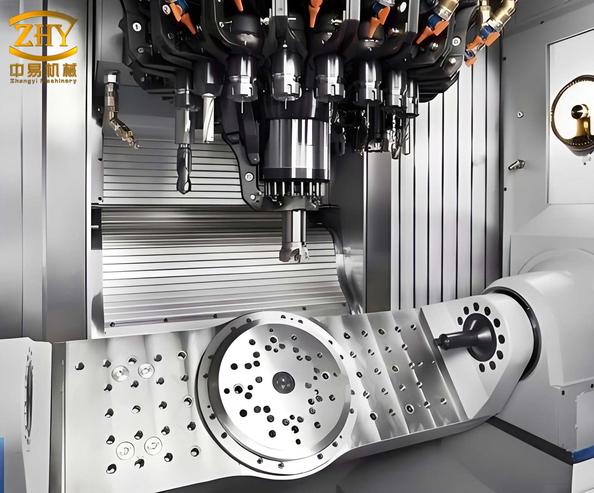
The image above illustrates a defect-free machine tool casting produced via the refined lost foam method. Its precise dimensions and smooth surface highlight the effectiveness of the discussed techniques. In addition to process parameters, material properties play a role. For instance, the foam density and coating permeability affect gas evolution and metal flow. I often use expanded polystyrene (EPS) foam with a density of 20-25 kg/m³ for machine tool castings, as it balances strength and vaporization rate. The coating thickness is kept between 0.5-1.0 mm to ensure gas permeability while preventing metal penetration. These factors can be summarized in a material selection table for machine tool casting.
| Material | Parameter | Typical Value | Impact on Casting |
|---|---|---|---|
| Foam Pattern | Density (kg/m³) | 20-25 | Lower density reduces gas volume but may compromise pattern strength |
| Coating | Thickness (mm) | 0.5-1.0 | Thicker coatings improve refractoriness but may hinder gas escape |
| Sand | Grain Size (AFS) | 45-55 | Finer sand increases compaction but reduces permeability |
| Metal | Pouring Temperature (°C) | 1350-1400 (for iron) | Higher temperature improves fluidity but increases gas generation |
Furthermore, simulation tools have been invaluable in optimizing machine tool casting processes. Using computational fluid dynamics (CFD), I model the filling and solidification stages to predict defect formation. For example, the pressure distribution in the mold can be simulated to identify areas prone to collapse. The governing equations include the Navier-Stokes equations for fluid flow and heat transfer equations for solidification. Simplified, the metal flow velocity \( u \) can be expressed as:
$$ \frac{\partial u}{\partial t} + u \cdot \nabla u = -\frac{1}{\rho_m} \nabla P + \nu \nabla^2 u + g $$
where \( \nu \) is the kinematic viscosity. By integrating these simulations with empirical data, I fine-tune parameters before actual production, reducing trial-and-error costs for machine tool casting projects.
In conclusion, the lost foam process offers immense potential for machine tool casting, but its success hinges on meticulous control of multiple variables. My experience shows that defects like skin penetration, collapse, and iron nodules can be mitigated through strategic gating design, optimized vibration parameters, and precise negative pressure management. For machine tool castings, particularly large components such as columns, I recommend a minimum sand cover of 150 mm, a negative pressure of 0.038-0.045 MPa, and a multi-stage vibration sequence as detailed in Table 3. Additionally, material selection and simulation aid in preempting issues. By adopting these practices, foundries can achieve high-quality machine tool castings with reduced scrap rates, enhancing productivity and competitiveness. The ongoing evolution of lost foam technology continues to push the boundaries of what is possible in machine tool casting, and I am committed to exploring further innovations in this field.
To summarize key formulas and parameters, I present a final table encapsulating the core relationships for machine tool casting via lost foam. This serves as a quick reference for practitioners aiming to optimize their processes.
| Aspect | Formula/Parameter | Description | Optimal Range |
|---|---|---|---|
| Gas Generation | \( V_g = \frac{m_f \cdot R \cdot T}{P \cdot M} \) | Volume of gas from foam decomposition | Minimize via foam density control |
| Buoyancy Force | \( F_b = (\rho_m – \rho_s) \cdot g \cdot V_d \) | Force tending to displace sand | Counteract with sand cover ≥150 mm |
| Gate Area | \( A_g = \frac{Q}{v} \) | Area of ingate for controlled flow | Based on pouring rate, v < 0.5 m/s |
| Negative Pressure | \( Q_g = \frac{k \cdot A \cdot \Delta P}{\mu \cdot L} \) | Gas evacuation rate | ΔP = 0.038-0.045 MPa |
| Sand Compaction | Vibration parameters (Table 3) | Ensures uniform sand density | Multi-stage with varying speeds |
Through continuous improvement and adaptation, the lost foam process will remain a cornerstone of advanced machine tool casting, enabling the production of durable, precise components essential for modern industry. My work in this area reinforces the value of integrating theoretical insights with hands-on experimentation to overcome challenges and achieve excellence in casting quality.