
The relentless advancement of the automotive industry demands continuous improvement in the production of safety-critical components. Among these, the brake caliper stands as a vital element of the disc braking system. Producing these components in high volume with consistent quality, excellent mechanical properties, and cost-effectiveness is a paramount challenge for foundries. This article details a comprehensive process optimization for manufacturing a spheroidal graphite cast iron (SG iron, or ductile iron) brake caliper, focusing on a strategic change in mold layout that significantly enhances yield and productivity without compromising the integrity of the final casting.
The component in question is a passenger vehicle brake caliper with a specified material grade equivalent to QT450-10. The casting is characterized by a complex geometry necessary for housing the brake piston and pads, with varying wall thicknesses and several functional bosses and mounting points. The single casting weight is approximately 3.02 kg, with overall dimensions of 185 mm x 74 mm x 163 mm. The successful production of spheroidal graphite cast iron components like this hinges on meticulous control over every stage of the process.
Technical Specifications and Material Requirements
The foundation of a robust casting process is a clear understanding of the material and performance specifications. For this spheroidal graphite cast iron caliper, the requirements are stringent to ensure reliability under cyclic mechanical and thermal stress.
| Element | Required Range (wt.%) |
|---|---|
| C | 3.3 – 3.9 |
| Si | 2.2 – 3.2 |
| Mn | 0.1 – 0.4 |
| P | ≤ 0.08 |
| S | ≤ 0.02 |
| Cu | ≤ 0.2 |
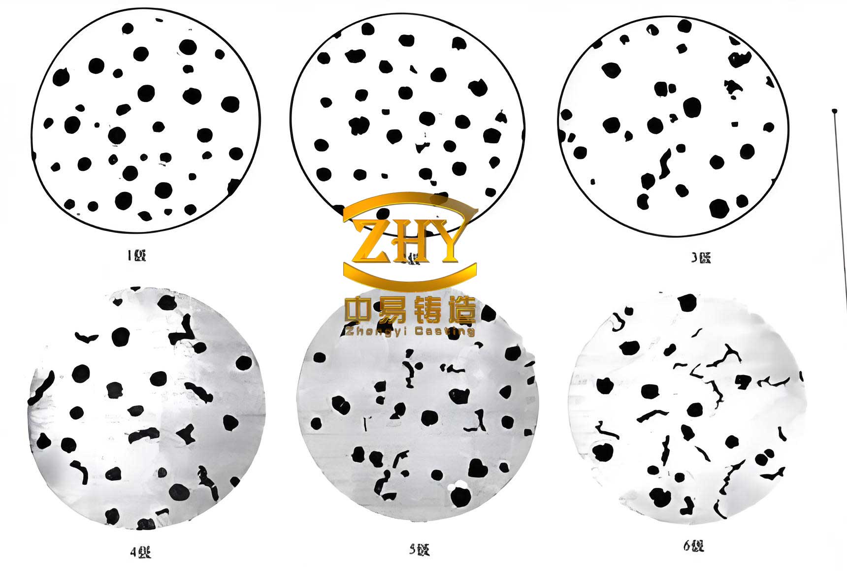
The metallographic structure is critical for the performance of spheroidal graphite cast iron. The specifications require a nodularity (percentage of graphite in nodular form) greater than or equal to 80%, with graphite size rated between 5 to 8 (according to relevant standards). The matrix should be primarily ferritic, with some pearlite acceptable, and must be free from detrimental carbides.
| Property | Minimum Requirement |
|---|---|
| Tensile Strength, Rm | 450 MPa |
| Yield Strength, Rp0.2 | 280 MPa |
| Elongation, A | 10% |
| Hardness | 143 – 217 HBW |
Furthermore, the casting must be sound, free from internal defects such as shrinkage porosity, cavities, cracks, and gross gas holes. Surface quality is also paramount, with no sand inclusions, slag holes, or other imperfections that could affect assembly or performance.
Foundry Process Design and Strategic Optimization
The production was based on a DISA 230B vertically parted, flaskless, shoot-squeeze molding machine. The standard plate dimensions for this machine are 650 mm x 535 mm, which sets the boundary conditions for the mold layout.
Mold Layout Innovation: From Vertical to Horizontal Bore Orientation
The conventional and initially attempted approach for casting such a caliper was to orient the component with its critical cylinder bore axis vertical. This orientation seems intuitive for feeding. However, within the fixed plate area, this arrangement allowed for a maximum of only 4 castings per mold. Attempting to place 6 castings with this orientation left insufficient space for an adequate gating system and resulted in critically low mold wall thickness between impressions, as the parts required significant horizontal space.
The breakthrough came from reorienting the casting so that the cylinder bore axis was placed horizontally. This simple but effective rotation reduced the footprint of each casting cluster on the pattern plate. Consequently, it became feasible to arrange three castings horizontally and two vertically, achieving a total of 6 castings per mold. To optimize the use of space and facilitate efficient gating and risering, four castings were placed in one direction and the remaining two were mirrored. This layout innovation directly increased the mold yield by 50% compared to the traditional method.
The process yield, or casting yield, is a key economic metric. It is calculated as the total weight of saleable castings divided by the total weight of metal poured (including gates and risers). The new layout achieved a process yield of 61.6%, representing a 19% absolute improvement over the yield attainable with the 4-casting layout. The improvement can be summarized as:
$$ \text{Yield Improvement} = \frac{\text{Yield}_{\text{new}} – \text{Yield}_{\text{old}}}{\text{Yield}_{\text{old}}} \times 100\% $$
Where, for this case, the improvement was significant.
| Layout Strategy | Castings per Mold | Approximate Process Yield | Key Limitation |
|---|---|---|---|
| Bore Vertical (Conventional) | 4 | ~42-43% | Space for gating/risers insufficient for 6 castings. |
| Bore Horizontal (Optimized) | 6 | 61.6% | Requires careful design of top and bottom gating. |
Riser Design for Sound Spheroidal Graphite Cast Iron
The horizontal orientation of the thick cylinder bore section allowed for the placement of a riser directly atop this major thermal center. Effective riser design is governed by the modulus principle, ensuring the riser solidifies after the casting section it is intended to feed. The casting modulus, \( M_c \), is calculated as the casting volume, \( V_c \), divided by its cooling surface area, \( S_c \).
$$ M_c = \frac{V_c}{S_c} $$
For the critical section (hot spot), the modulus \( M_{hs} \) was calculated to be 5.9 mm. To ensure adequate feeding for this spheroidal graphite cast iron part, the riser modulus \( M_r \) should satisfy:
$$ M_r = 1.2 \times M_{hs} $$
This gives a required \( M_r \geq 7.08 \) mm. Due to spatial constraints on the pattern plate, a spherical riser with a diameter of 58 mm was initially considered. To further enhance its feeding capacity, the riser was modified with a 15 mm thick padding at its connection to the casting. The final riser modulus was calculated to be 8.6 mm, exceeding the requirement and ensuring it would remain liquid to feed the shrinkage of the casting during solidification. A hot riser design was employed, meaning it receives direct metal flow from the gating system.
Gating System Design for Controlled Filling
While the top-located hot riser is excellent for feeding, introducing metal only from the top of a mold can lead to turbulent flow, oxide formation, and sand erosion—all detrimental to the surface quality of the spheroidal graphite cast iron casting. To mitigate this, a combined gating system was designed.
The system features a primary top gating that feeds directly into the risers to keep them hot. Additionally, a thin, bottom gating system was introduced. This bottom gate, designed as a 1 mm thick skim gate at the base of the casting cavity, opens first during pouring. It allows calm, bottom-up filling of the mold cavity, reducing turbulence. The top gates then become active, ensuring the risers are filled with hot metal. This dual approach promotes temperature gradient favorable for directional solidification towards the risers.
A semi-choked (pressurized) gating system ratio was adopted to promote a non-turbulent flow in the runners. The designed ratio of cross-sectional areas was:
$$ \Sigma F_{\text{sprue}} : \Sigma F_{\text{runner}} : \Sigma F_{\text{gate}} = 1 : 0.7 : 1.2 $$
With specific areas of 500 mm², 350 mm², and 600 mm² for the sprue, runner, and in-gates (total), respectively. To economize on space, one sprue fed four castings, and a separate sprue fed the remaining two. Pouring parameters were set with a starting temperature of 1420°C, a finishing temperature above 1370°C, and a target pour time of 8 seconds per mold.
Numerical Simulation for Process Validation
Prior to costly production trials, the entire process was simulated using MAGMAsoft, a dedicated casting simulation software. The simulation modeled the filling and solidification sequences for the spheroidal graphite cast iron.
Filling Analysis: The simulation confirmed that the combined gating system worked as intended. Metal initially filled the cavity calmly from the bottom gate, followed by the top gates. The temperature field during filling showed a progressive advance without severe turbulence or air entrapment, validating the design for surface quality.
Solidification Analysis: The most critical output was the prediction of shrinkage defects. The solidification sequence showed a clear directional progression from the extremities of the casting towards the strategically placed risers. The simulation results indicated no isolated liquid pools (hot spots) within the main body of the casting. The final regions to solidify were within the risers themselves, confirming their efficacy. This virtual validation provided high confidence that the optimized layout and feeding design would produce sound spheroidal graphite cast iron castings, minimizing the risk of internal shrinkage porosity.
Production Implementation and Quality Control
With the simulation providing a green light, the process was implemented on the foundry floor. Consistent quality in high-volume production of spheroidal graphite cast iron requires strict control over all ancillary processes.
Molding Sand Preparation
A green sand system using bentonite clay as the binder was employed. Consistent sand properties are essential for achieving good definition, surface finish, and avoiding defects like scabbing or sand inclusions. The sand was mixed in a 3-ton capacity rotor mixer with precise sequencing and timing. Properties were tightly controlled within the following ranges:
| Property | Control Range |
|---|---|
| Moisture Content | 3.2 – 3.4 % |
| Compactability | 38 – 42 % |
| Green Compressive Strength | 0.17 – 0.21 MPa |
| Permeability | 100 – 120 |
| Active Bentonite | 7 – 9 % |
| Loss on Ignition | 3 – 6 % |
Melting, Nodularizing, and Inoculation of Spheroidal Graphite Cast Iron
The charge consisted of 50% returns (own spheroidal graphite cast iron scrap), 20% pig iron (Q10 grade), and 30% steel scrap. Carbon recovery was ensured by adding recarburizer with the steel scrap charge in the medium-frequency induction furnace. The base iron was superheated to 1535-1555°C and held to ensure complete dissolution and homogeneity before tapping at 1495-1525°C. The target base iron chemistry prior to treatment is shown below:
| Element | C | Si | Mn | P | S |
|---|---|---|---|---|---|
| wt.% | 3.80-3.85 | 2.00-2.10 | 0.25-0.30 | ≤0.06 | ≤0.025 |
The nodularizing treatment was performed using the cored wire injection method. A magnesium-bearing wire (Mg: 29.5-32.5%, RE: 2.0-2.5%) was injected into the transferred iron ladle. This method offers excellent and consistent magnesium recovery with minimal fume and flare. Key treatment parameters were:
- Wire Injection Speed: 14.5 m/min ± 0.15
- Treatment Temperature: 1430-1450°C
- Post-inoculation Pouring Temperature: 1400-1360°C
A triple inoculation strategy was applied to guarantee a high nodule count and prevent carbide formation in this spheroidal graphite cast iron:
- Pre-inoculation: 0.2% FeSiBa (2.6-4.5 mm) added during tapping from the furnace.
- Post-inoculation: 0.3% FeSiBa (0.6-2.5 mm) added during transfer to the pouring ladle.
- Late Inoculation: A controlled stream inoculation of fine FeSiBa (0.2-0.5 mm) at 3 g/s during the actual pouring of each mold.
This robust treatment and inoculation practice is critical for achieving the required ferritic matrix and high ductility in the final spheroidal graphite cast iron component.
Quality Verification and Production Results
Castings produced from the optimized process underwent rigorous inspection to verify compliance with all specifications.
Chemical and Metallographic Analysis
Spectrochemical analysis confirmed the final chemistry was within the specified range, with residual magnesium levels typically between 0.040% and 0.050%. Microstructural evaluation was performed on samples taken from a critical 20 mm thick section of the casting body.
The results were excellent: nodularity consistently exceeded 90%, well above the 80% requirement. Graphite was predominantly in sizes 6-7. The matrix structure was approximately 75% ferrite and 25% pearlite, with no observed free carbides. This “bull’s-eye” structure (ferrite surrounding graphite nodules in a pearlitic matrix) is ideal for achieving the combination of strength and ductility required for spheroidal graphite cast iron brake components.
Mechanical Properties
Tensile tests were conducted on separately cast keel blocks (as per standard practice) and also on test bars machined from the non-critical mounting lugs of actual castings to verify the in-situ properties. Hardness was measured on the casting body. The results consistently met or exceeded specifications.
| Sample Source | Tensile Strength (MPa) | Yield Strength (MPa) | Elongation (%) | Hardness (HBW) |
|---|---|---|---|---|
| Keel Block (Avg) | 480 – 495 | 330 – 340 | 13 – 18 | 165 – 185 |
| Casting Lug (Example) | 476 | 336 | 15.6 | 180 |
Internal and Surface Integrity
Non-destructive testing via X-ray radiography revealed no internal shrinkage or gas-related defects in the critical sections of the casting. Furthermore, destructive testing involving sectioning and dye penetrant inspection of the cut surfaces confirmed the soundness of the internal structure, with no subsurface shrinkage. Surface quality was excellent, free from sand burns, erosion, or cold laps, attesting to the effectiveness of the controlled filling gating design.
Conclusion
The successful high-volume production of this automotive brake caliper demonstrates a significant optimization in spheroidal graphite cast iron foundry practice. By fundamentally rethinking the pattern layout—changing the cylinder bore orientation from vertical to horizontal—it was possible to increase the number of castings per mold from 4 to 6. This directly translated to a 50% increase in mold productivity and a 19% improvement in metal yield, offering substantial economic benefits.
This layout change was strategically supported by a riser design based on modulus calculations, a dual top-and-bottom gating system for controlled filling, and a robust melting and treatment regimen for spheroidal graphite cast iron. Numerical simulation proved to be an invaluable tool for de-risking the process change before implementation. Rigorous production controls and validation confirmed that all mechanical, metallurgical, and integrity specifications were consistently achieved, with a controlled scrap rate well below 2%. This case study underscores the importance of holistic process engineering in achieving both quality and efficiency in the modern production of complex spheroidal graphite cast iron components.