
In the electrical machinery and appliance industry, reducing hysteresis losses and associated magnetic heating effects has long been a critical challenge. Traditionally, non-ferrous metals like aluminum and copper were employed for cast iron parts, but their high cost drove the search for alternatives. With advancements in technology, austenitic cast iron or austenitic cast steel has gradually replaced these materials. Austenitic non-magnetic cast iron is an alloyed cast iron with low permeability, typically denoted by μ < 1.05. In Europe and America, non-magnetic cast iron parts relied heavily on high nickel content to ensure the stability of the austenitic matrix. However, due to nickel’s expense, recent developments have focused on substituting part of the nickel with other elements, such as manganese. In our extensive research and production experience, we have explored the use of manganese-based systems to achieve stable austenitic structures at room temperature, significantly reducing costs while maintaining performance. This article delves into the influence of chemical composition on the properties of non-magnetic cast iron parts and details the metal mold casting process we’ve refined over two decades.
The key to obtaining austenitic non-magnetic cast iron lies in its chemical composition, which determines the stability of the austenite phase at ambient temperatures. Grey cast iron typically transforms from austenite at high temperatures to pearlite, ferrite, or carbides upon cooling, but elements like nickel and manganese can expand the austenite region and lower the transformation temperature. For cost-effectiveness, we focused on manganese as the primary austenite stabilizer. Below, I summarize the effects of various elements, supported by tables and formulas, to guide the design of non-magnetic cast iron parts.
Chemical Composition and Its Impact on Non-Magnetic Cast Iron Parts
Manganese (Mn) is the most crucial element for stabilizing austenite in non-magnetic cast iron parts. However, its content must be carefully controlled. Insufficient manganese leads to austenite decomposition into ferrite or martensite, increasing permeability. Excessive manganese promotes carbide formation, which hardens the material and complicates machining. The relationship between manganese content and magnetic permeability (μ) can be expressed empirically. Based on our trials, the permeability tends to follow a trend where:
$$ \mu \propto \frac{1}{[Mn]^n} \quad \text{for optimal ranges, but rises sharply at extremes} $$
Here, [Mn] denotes the weight percentage of manganese, and n is an exponent derived from experimental data. Table 1 illustrates the effect of manganese content on permeability, measured in our foundry for various cast iron parts.
| Manganese Content (wt%) | Magnetic Permeability (μ) | Base Microstructure |
|---|---|---|
| 8.0 – 9.0 | 1.02 – 1.03 | Austenite with minimal carbides |
| 9.5 – 10.5 | 1.03 – 1.05 | Austenite with moderate carbides |
| 11.0 – 12.0 | 1.06 – 1.10 | Austenite with significant carbides |
| >12.5 | >1.15 | Chill formation, white iron |
Carbides themselves influence magnetic properties. In experiments where we fixed the composition but varied cooling rates to alter carbide volume fraction, we observed that permeability increases with carbide content. This relationship can be approximated as:
$$ \mu = \mu_0 + k \cdot V_c $$
where μ₀ is the permeability of pure austenite, k is a constant (approximately 0.05 per percentage of carbide volume), and V_c is the volume fraction of carbides. Table 2 shows data from such tests on cast iron parts.
| Carbide Volume Fraction (%) | Magnetic Permeability (μ) | Hardness (HB) |
|---|---|---|
| 0 – 2 | 1.02 – 1.03 | 120 – 150 |
| 3 – 5 | 1.04 – 1.06 | 150 – 180 |
| 6 – 8 | 1.07 – 1.10 | 180 – 220 |
| >9 | >1.12 | >220 |
Carbon (C) and silicon (Si) are strong graphitizing elements. They help counteract the chilling tendency caused by high manganese, preventing white iron formation. However, excessive silicon can decompose austenite into martensite, raising permeability. Our studies indicate that for a typical composition with Mn around 10%, the silicon content should be limited to 2.0-2.5% to maintain μ < 1.05. A useful empirical rule is:
$$ [Si]_{\text{max}} = 0.25 \times [Mn] – 0.5 $$
Copper (Cu) enhances austenite stability and refines grain structure. When added in amounts of 1.5-2.5%, it helps stabilize the matrix without significantly affecting permeability. Table 3 summarizes the effect of copper on magnetic properties for cast iron parts with fixed manganese and carbon levels.
| Copper Content (wt%) | Magnetic Permeability (μ) | Microstructure Notes |
|---|---|---|
| 0.5 – 1.0 | 1.04 – 1.06 | Austenite, some decomposition |
| 1.5 – 2.0 | 1.02 – 1.04 | Stable austenite, fine grains |
| 2.5 – 3.0 | 1.03 – 1.05 | Austenite with slight carbide precipitation |
Additionally, the ratio of manganese to copper is critical for machinability. We derived a formula based on practical experience:
$$ \frac{[Mn]}{[Cu]} \approx 5.5 \quad \text{for optimal machinability} $$
If this ratio exceeds 6, machining tends to cause chipping and tool wear in cast iron parts. For instance, in a ring-shaped non-magnetic cast iron part we produced, poor machinability was traced to a ratio of 6.2, leading to adjustments in composition.
Aluminum (Al) is a graphitizing element that dissolves in austenite. Typically, we add 0.5-1.0% to improve fluidity and reduce chilling. However, amounts above 1.5% can induce martensite, increasing permeability. Sulfur (S) and phosphorus (P) are generally kept low; sulfur is harmful, while phosphorus enhances fluidity but does not affect magnetic properties significantly.
Based on these principles, we developed a manganese-copper system for non-magnetic cast iron parts. Compared to nickel-based systems, this reduces material costs by over 30% while achieving similar performance. Table 4 compares typical compositions used in our production for large cast iron parts like stator pressure rings.
| Element | Our Mn-Cu System (wt%) | Traditional Ni System (wt%) | Effect on Cast Iron Parts |
|---|---|---|---|
| Carbon (C) | 2.8 – 3.2 | 2.5 – 3.0 | Graphitization, strength |
| Silicon (Si) | 2.0 – 2.5 | 1.5 – 2.0 | Graphitization, fluidity |
| Manganese (Mn) | 9.5 – 11.0 | 1.0 – 2.0 | Austenite stabilization |
| Copper (Cu) | 1.8 – 2.2 | 0 – 0.5 | Grain refinement, stability |
| Nickel (Ni) | 0 – 0.5 | 18 – 22 | Austenite stabilization (replaced) |
| Aluminum (Al) | 0.5 – 1.0 | 0 – 0.3 | Graphitization, fluidity |
Metal Mold Casting of Non-Magnetic Cast Iron Parts
Metal mold casting, also known as permanent mold casting, is employed for producing large, high-integrity non-magnetic cast iron parts. While this method can exacerbate shrinkage and cracking tendencies due to rapid cooling, we have optimized the process to leverage its advantages: faster cooling allows for lower manganese content to achieve stable austenite, reducing alloy costs. Over two decades, we have successfully cast over a thousand tons of non-magnetic cast iron parts, with a yield exceeding 98%. I will detail our approach using the example of a stator pressure ring for a 300 MW steam turbine generator.
The technical requirements for such cast iron parts include: bending strength ≥ 400 MPa, hardness 120-180 HB, magnetic permeability μ ≤ 1.05, and freedom from defects like cracks, porosity, shrinkage, sand inclusions, and slag. To meet these, we focus on mold design and operational工艺.
Metal Mold Design Considerations
Before designing the mold, we review the part drawing to modify features unsuitable for metal mold casting. For instance, fillet radii are increased from R5 to R10, and cross-shaped ribs are changed to T-shapes to reduce hot spots. Draft angles are amplified for easier demolding, especially for large cast iron parts. Table 5 lists our draft angle standards.
| Section Height (mm) | Draft Angle (degrees) |
|---|---|
| ≤ 100 | 1 – 2 |
| 101 – 200 | 2 – 3 |
| 201 – 500 | 3 – 5 |
| > 500 | 5 – 7 |
Mold wall thickness is critical for strength, rigidity, and heat transfer. Too thin, and the mold may warp or fuse with the metal; too thick, and thermal stresses cause cracks. We use two methods: empirical values (Table 6) and a calculation formula.
| Cast Iron Part Thickness (mm) | Mold Wall Thickness (mm) |
|---|---|
| 10 – 20 | 20 – 30 |
| 21 – 50 | 30 – 60 |
| 51 – 100 | 60 – 100 |
| > 100 | 100 – 150 |
The formula we apply is:
$$ t_m = 2 \times t_p + 20 $$
where t_m is the mold wall thickness in mm, and t_p is the cast iron part thickness in mm. This ensures adequate heat dissipation for non-magnetic cast iron parts.
Shrinkage allowances must account for both the mold’s contraction and the cast iron part’s contraction. For sand casting, iron shrinkage is typically 1.0-1.5%, but for metal mold casting of non-magnetic cast iron, we use 1.2-1.8%. Thus, the patternmaker’s rule is to allow a total shrinkage of 2.0-2.5% when creating the wooden model.
Mold material selection is based on durability and thermal properties. We prefer low-carbon low-silicon cast iron or medium-strength cast iron for molds, as they offer good resistance to thermal cracking. Table 7 compares options.
| Mold Material | Expected Life (cycles) | Thermal Crack Resistance |
|---|---|---|
| Low-carbon low-silicon cast iron | 5,000 – 10,000 | Moderate |
| Medium-strength cast iron | 8,000 – 15,000 | Good |
| High-silicon cast iron | 3,000 – 6,000 | Poor |
| Ductile iron | 10,000 – 20,000 | Excellent |
In the mold design, we incorporate four tapered risers (top-small, bottom-large) with a 5° slope. The riser openings in the mold are enlarged by 10-15 mm per side to accommodate insulating sand, which enhances feeding and reduces shrinkage defects. The gating system uses a bottom-pour design with four ingates to ensure smooth, non-turbulent filling—critical for non-magnetic cast iron parts prone to oxidation and slag inclusion. The gating ratio (sprue:runner:ingate) is set at 1:1.5:1.2, larger than for gray iron, to accommodate the alloy’s viscosity. For the stator pressure ring, dimensions are: ingates 30 mm × 15 mm (4 pieces), runner trapezoidal 40 mm × 30 mm, sprue diameter 50 mm. To minimize stress and facilitate demolding, we use green sand cores for internal features.
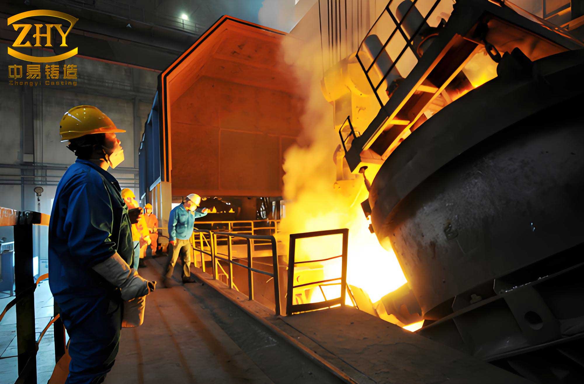
Operational Process for Casting Non-Magnetic Cast Iron Parts
Mold preparation begins with cleaning the cavity using wire brushes to remove old coatings and rust, followed by dusting. A uniform coating of about 0.5 mm thickness is applied via brush. We use two coating formulations depending on part thickness, as shown in Table 8.
| Component | Coating for Thin Walls (<50 mm) | Coating for Thick Walls (>50 mm) |
|---|---|---|
| Silicon powder (wt%) | 40 | 30 |
| Graphite (wt%) | 20 | 25 |
| Linseed oil (wt%) | 10 | 15 |
| Fireclay (wt%) | 20 | 20 |
| Water (wt%) | 10 (adjust to density 1.2-1.3 g/cm³) | 10 (adjust to density 1.1-1.2 g/cm³) |
Preheating the mold is essential to dry the coating, reduce gas holes and chill, and extend mold life. We preheat to 200-250°C, measured with surface thermometers or by observing soapstone marks: at 150°C, marks turn light yellow in 30 seconds; at 200°C, yellow; at 250°C, dark brown. Once preheated, the mold must be closed and poured promptly.
Mold assembly and pouring involve aligning with pins or marks. Ladle slag is thoroughly skimmed before pouring. For non-magnetic cast iron parts, the pouring temperature is maintained at 1350-1380°C. We pour at a steady, uninterrupted rate to ensure uniform rise in the cavity. When the metal reaches 80% of the riser height, we pause, then top up the riser 2-3 times to keep it hot for effective feeding.
Demolding occurs after a dwell time of 30-40 minutes, when the cast iron part temperature drops to about 900°C. The part is carefully extracted and placed in a sand bed, lightly covered to avoid rapid cooling and cracking. This gradual cooling helps maintain austenite stability in the cast iron parts.
Case Study: Stator Pressure Ring Production
For a 300 MW generator stator pressure ring, with dimensions roughly 2000 mm in diameter and 150 mm thickness, we use the composition: C 3.0%, Si 2.2%, Mn 10.5%, Cu 2.0%, Al 0.8%, P < 0.05%, S < 0.03%. The mold is made of medium-strength cast iron with a wall thickness of 120 mm. After casting, the part achieves a bending strength of 420-450 MPa, hardness 130-160 HB, and permeability μ = 1.03-1.04, well within specifications. Over twenty years, we have produced such cast iron parts with consistent quality, saving approximately $500,000 in nickel costs alone.
Conclusion
Through systematic research and实践, we have demonstrated that manganese-based non-magnetic cast iron parts can effectively replace nickel-based alloys in electrical applications. By optimizing chemical composition—particularly the balance of manganese, copper, carbon, and silicon—we achieve stable austenitic structures with low permeability. Metal mold casting, despite its challenges, proves viable for large cast iron parts when combined with proper design, coating, preheating, and cooling controls. Our process has yielded over a thousand tons of defect-free cast iron parts, with mechanical properties exceeding requirements and magnetic performance meeting stringent standards. This approach not only reduces costs but also leverages abundant elements, contributing to sustainable manufacturing in the electrical industry. Future work may explore further substitutions and advanced casting techniques to enhance the performance and affordability of non-magnetic cast iron parts.