
In the intricate world of automotive powertrains, the gearbox housing stands as a silent sentinel. Its role extends far beyond a mere container; it is the foundational structure that ensures precise alignment of gears and bearings, contains lubricants, and bears significant operational loads and vibrations. The manufacturing integrity of this component is paramount. Among the various production methods, sand casting remains a predominant and highly adaptable process for creating such complex, medium-to-large sand casting products. From my experience in foundry engineering, achieving a defect-free gearbox housing requires a meticulously designed process chain, from pattern making to shakeout, coupled with a robust system for fault diagnosis and prevention. This article delves into the core aspects of the sand casting process for gearbox housings and presents a systematic approach to diagnosing common casting defects.
The gearbox housing, often a box seat or a split casing, typically features a complex geometry with varying wall thicknesses, internal ribs for stiffness, precisely located bearing seats (often called “bearing caps” or “瓦口” in the original text), and numerous mounting flanges. These characteristics make it a classic candidate for sand casting. The material choice is critical, with gray iron, ductile iron, and aluminum alloys being the most common, offering a favorable balance of strength, damping capacity, machinability, and cost-effectiveness for high-volume sand casting products.
The Sand Casting Process: A Step-by-Step Breakdown for Complex Housings
The journey of a gearbox housing from a drawing to a finished casting involves a series of interconnected steps. The reliability of the final component is directly tied to the control exerted at each stage. The generalized process flow can be summarized as follows, with particular emphasis on steps crucial for housing castings:
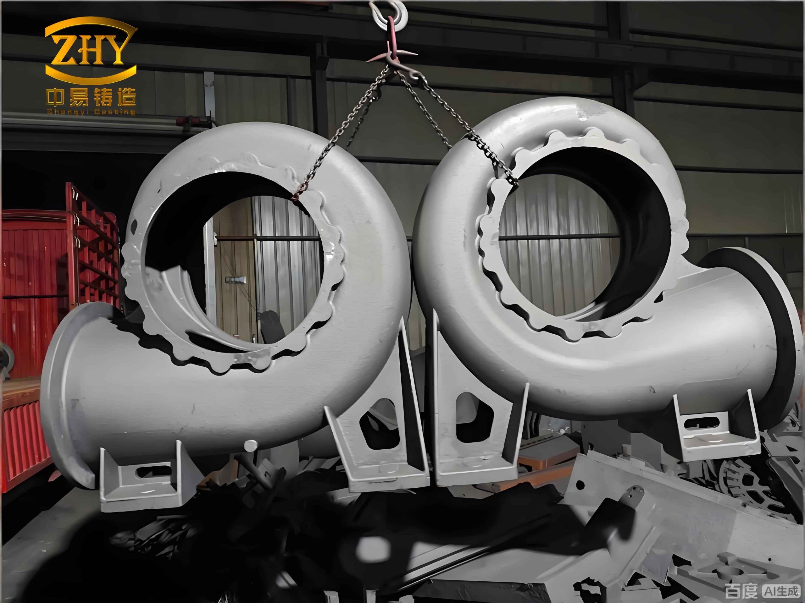
| Process Stage | Key Activities & Considerations for Gearbox Housings |
|---|---|
| 1. Pattern & Core Box Design | Creation of a physical model (pattern) of the housing and separate models (core boxes) for its internal cavities. Must account for shrinkage, machining allowances, and draft angles. Often made from metal (e.g., aluminum, cast iron) for durability in high-volume production of sand casting products. |
| 2. Molding | Using the pattern to form the negative impression (mold cavity) in compacted sand within a flask. For housings, a two-part flask (cope and drag) with the parting line chosen to maximize simplicity and ease of molding is common. The “drag” (bottom half) often contains the main body, while the “cope” (top half) forms the top features. |
| 3. Core Making | Fabricating sand cores that will define the internal passages, oil galleries, and hollow sections of the housing. Cores are made separately in core boxes using sand mixed with binders, then baked for strength. |
| 4. Core Setting & Mold Assembly | Placing the cured cores into the mold cavity on designed core prints. This is a critical step for dimensional accuracy of bearing bores and internal walls. The cope is then placed over the drag to close the mold. |
| 5. Melting & Pouring | Melting the chosen alloy to the correct temperature and chemistry. The molten metal is then poured into the assembled mold through a designed gating system. |
| 6. Cooling & Shakeout | Allowing the casting to solidify and cool sufficiently within the mold. The sand mold is then broken away, and the casting is removed. |
| 7. Cleaning & Finishing | Removing the gating system (gates, risers), core sand residues, and surface imperfections via cutting, grinding, and shot blasting. |
| 8. Inspection & Heat Treatment | Non-destructive testing (visual, dimensional, radiographic) and necessary heat treatments (e.g., stress relieving, annealing) to achieve required mechanical properties. |
Critical Process Design Elements for Gearbox Housings
1. Gating System Design: Ensuring Smooth Filling
For a component as critical as a gearbox housing, a turbulent metal flow during pouring is unacceptable as it leads to slag entrapment and oxide formation. Therefore, a bottom-gating or step-gating system is often preferred. This design introduces molten metal at the bottom of the mold cavity, allowing it to fill upward in a controlled, quasi-laminar manner, which minimizes turbulence and promotes favorable temperature gradients for directional solidification. Key calculations govern this design:
a) Minimum Sprue Height (Pressure Head): The sprue must provide sufficient metallostatic pressure to fill the mold completely, especially the upper sections and thin walls. A simplified check involves ensuring the effective pressure head \( H_p \) at the top of the casting meets a minimum requirement. If we consider the distance from the sprue base to the farthest and highest point in the mold cavity as \( L \), a rule of thumb based on pressure angle \( \alpha \) (typically 6°-10°) can be applied:
$$
H_{p(min)} \approx L \cdot \tan \alpha
$$
For a housing where \( L = 1100 \) mm and \( \alpha = 6^\circ \), we get \( H_{p(min)} \approx 1100 \times \tan(6^\circ) \approx 116 \) mm. Therefore, the sprue height must be designed to provide an effective pressure head significantly greater than this value, often by 20-30%, to ensure robust filling.
b) Pouring Time & Fill Rate: An optimal pouring time \( t \) balances the risk of cold shuts (if too slow) with mold erosion and turbulence (if too fast). Empirical formulas based on casting weight \( W \) (kg) and average wall thickness \( T \) (mm) are used. One common formula for medium-sized steel and iron castings is:
$$
t = S \cdot \sqrt[3]{W} \cdot \sqrt{T}
$$
Where \( S \) is an empirical coefficient (often around 2.0 for cast iron). For a housing weighing \( W = 500 \) kg with \( T = 20 \) mm, the estimated pouring time would be \( t \approx 2.0 \times \sqrt[3]{500} \times \sqrt{20} \approx 2.0 \times 7.94 \times 4.47 \approx 71 \) seconds. The fill rate \( v \) in the mold cavity is then \( v = C / t \), where \( C \) is the height of the casting. This rate must be compared against recommended values for the alloy to prevent defects.
c) Choke Area Calculation: The cross-sectional area at the smallest point of the gating system (often the sprue base or a choke in the runner) controls the flow rate. It can be derived from the basic fluid flow equation:
$$
A_{choke} = \frac{W}{\rho \cdot t \cdot \mu \cdot \sqrt{2gH}}
$$
Where:
\( A_{choke} \) = Choke area (m²)
\( W \) = Casting weight (kg)
\( \rho \) = Liquid metal density (kg/m³)
\( t \) = Pouring time (s)
\( \mu \) = Discharge coefficient (accounting for friction losses, typically 0.6-0.8)
\( g \) = Acceleration due to gravity (9.81 m/s²)
\( H \) = Effective sprue height (m)
Using the prior example with \( W=500 \) kg, \( \rho=7000 \) kg/m³ (iron), \( t=71 \) s, \( \mu=0.7 \), and \( H=0.3 \) m, the calculation yields an \( A_{choke} \) of approximately \( 2.6 \times 10^{-3} \) m² or 26 cm². The total ingate area is then typically 1.5 to 2 times the choke area to ensure the choke remains the controlling point and metal enters the cavity at a reduced velocity.
2. Core Design and Assembly
The internal geometry of a gearbox housing is almost always formed by sand cores. For complex housings, a single, massive core is impractical for manufacturing and venting. Therefore, the core assembly is strategically split into several segments. A typical breakdown for a housing might include:
- Main Cavity Core: Forms the primary interior void.
- Bearing Bore Cores (瓦口): These are precision cores that create the seats for gears and bearings. They are often made from higher-quality sand or even shell cores for better surface finish and dimensional stability.
- Oil Gallery and Rib Cores: Smaller cores that create internal passages and reinforcing ribs.
These cores are assembled using locating prints and adhesives before being placed into the mold. Proper core venting using wax strings or vent rods is essential to allow gases generated during pouring to escape, preventing core blows.
3. Pattern Engineering for Production
For mass production of sand casting products like housings, metal patterns (aluminum or cast iron) are mandatory for dimensional consistency and longevity. Key design principles include:
- Lightweighting with Rigidity: Patterns are designed as hollow shells with internal ribs (“strengthening ribs”). The wall thickness \( \gamma \) can be estimated from the pattern’s overall dimensions. An empirical formula is \( \gamma = k(1 + 0.008D) \), where \( D \) is the pattern’s approximate length or diameter in mm, and \( k \) is a material constant (e.g., ~5 for cast iron). For a housing pattern with \( D = 1200 \) mm, \( \gamma \approx 5 \times (1 + 9.6) \approx 53 \) mm, which would then be refined based on structural analysis.
- Incorporation of Loose Pieces: Undercuts like side flanges, lifting lugs, or deep pockets are molded using separate “loose pieces” that are withdrawn after molding but before the main pattern.
- Precision Core Prints: The pattern includes core prints that are machined to tight tolerances to ensure the cores sit accurately in the mold.
Systematic Fault Diagnosis in Sand Casting of Housings
Despite careful planning, defects can occur. A systematic diagnostic approach is vital for continuous improvement. Below is a detailed analysis of common defects in sand casting products like gearbox housings, their root causes, and preventive measures.
| Defect Category | Visual/Symptomatic Description | Primary Root Causes | Corrective & Preventive Actions |
|---|---|---|---|
| Blowholes & Pinholes | Smooth-walled, spherical or elongated cavities near the casting surface or just below it. Often discovered after machining. |
|
|
| Sand Inclusions (Sandholes) | Irregular cavities or surface imperfections filled with loose or sintered sand. |
|
|
| Shrinkage Porosity (Macro-shrinkage) | Irregular, dendritic-shaped cavities often located in hot spots (heavy sections, junction areas). Interior can be rough or spongy. |
|
|
| Cold Shuts & Misruns | Linear discontinuities or incomplete filling, often with rounded edges, where two metal streams failed to fuse. |
|
|
| Core Shift & Dimensional Variation | Walls of unequal thickness, misaligned features, or out-of-tolerance bearing bores. |
|
|
Process Optimization and Material Considerations
Beyond defect prevention, the overall quality and performance of gearbox housing sand casting products are enhanced by process optimization and correct material science. Computer simulation software (e.g., MAGMA, ProCAST) is now indispensable for virtual prototyping. It allows engineers to simulate filling, solidification, and stress development, identifying potential shrinkage zones, hot tears, and cold shuts before any metal is poured. This enables optimization of the gating and risering system digitally, saving significant cost and time.
Material selection is driven by application requirements:
- Gray Iron (GG/GL): Excellent damping capacity, good wear resistance, and low cost. Ideal for heavy-duty, vibration-sensitive applications.
- Ductile Iron (GGG): Higher strength and toughness than gray iron, with good machinability. Used where higher mechanical loads are expected.
- Aluminum Alloys (e.g., A356, A319): Significant weight reduction, good corrosion resistance, and excellent thermal conductivity. Requires careful gating design due to higher shrinkage and oxidation tendency.
The properties of these materials as sand casting products are not intrinsic; they are heavily influenced by the casting process itself. For instance, the cooling rate affects the microstructure (e.g., graphite flake size in iron, dendrite arm spacing in aluminum), which in turn determines tensile strength and elongation. Therefore, controlling solidification through chills and risers is a metallurgical tool as much as a defect-prevention one.
Future Trends and Concluding Remarks
The foundry industry is evolving with advancements in binder technology (e.g., more environmentally friendly inorganic binders), 3D sand printing for complex cores and even entire molds, and real-time process monitoring using IoT sensors. These technologies promise to further improve the dimensional accuracy, surface finish, and consistency of complex sand casting products like gearbox housings, while also reducing waste and energy consumption.
In conclusion, the production of a high-integrity gearbox housing via sand casting is a testament to the synergy of empirical foundry knowledge and modern engineering principles. It demands a holistic approach that integrates robust gating and riser design based on fluid flow and solidification science, precise pattern and core engineering, stringent control over sand and molten metal properties, and a disciplined system for diagnosing and eliminating defects. By viewing the housing not just as a component but as a premier example of engineered sand casting products, foundries can achieve the levels of quality, reliability, and performance required by the modern automotive industry. The continuous interplay between process design, fault diagnosis, and technological adoption remains the cornerstone of excellence in this field.