
As a foundry engineer specializing in non-ferrous alloy casting, I have spent years refining the sand casting process for critical marine components, particularly valve shells. Among these, silicon brass ZCuZn16Si4 stands out due to its excellent casting properties and corrosion resistance, making it ideal for marine applications like through-hull valves. These valves are essential for controlling ballast water in submersibles, and any leakage can compromise safety. Thus, producing defect-free sand casting parts is paramount. In this article, I will delve into the intricacies of sand casting silicon brass valve shells, focusing on preventing common defects such as cold shuts, shrinkage porosity, and oxide inclusions. I will share principles, case studies, and practical insights, emphasizing how proper design and execution yield reliable sand casting parts. Throughout, I will highlight the keyword ‘sand casting parts’ to underscore its importance in manufacturing.
Sand casting is a versatile and cost-effective method for producing complex metal parts, especially for low to medium volumes. For marine valve shells, which often have intricate internal passages and varying wall thicknesses, sand casting offers the flexibility needed to achieve precise geometries. However, the process requires careful consideration of alloy behavior, gating and risering design, and cooling control. Silicon brass, specifically ZCuZn16Si4, is a preferred material due to its superior fluidity, low shrinkage, and good pressure tightness. These properties reduce the risk of defects in sand casting parts, but they must be harnessed through optimized工艺. In my experience, the key lies in balancing sequential solidification with efficient filling, and this article will explore how to achieve that balance.
Let me begin by analyzing the characteristics of silicon brass ZCuZn16Si4. This alloy is a type of special brass where silicon improves castability and mechanical properties. The chemical composition and room-temperature mechanical properties for sand casting are standardized, as shown in Table 1. Silicon content between 2.5% and 4.5% enhances fluidity and reduces oxidation tendency, while copper (79-81%) and zinc (balance) provide strength and ductility. The low linear and volumetric shrinkage compared to other brasses, such as manganese brass, minimizes hot tearing and shrinkage defects in sand casting parts. This can be quantified using shrinkage formulas. For instance, the linear shrinkage rate for ZCuZn16Si4 in sand casting is approximately 1.2% to 1.5%, which I account for in pattern making. The volumetric shrinkage can be estimated using the equation for solidification contraction: $$ \Delta V = V_0 \cdot \beta \cdot (T_{\text{liquidus}} – T_{\text{solidus}}) $$ where $\Delta V$ is the volume change, $V_0$ is the initial volume, $\beta$ is the coefficient of thermal contraction, and $T$ represents temperatures. For silicon brass, $\beta$ is relatively low, around 0.04 to 0.06 per unit volume, reducing the demand for extensive risering.
| Element | Composition (wt%) |
|---|---|
| Copper (Cu) | 79.0 – 81.0 |
| Silicon (Si) | 2.5 – 4.5 |
| Zinc (Zn) | Balance |
| Property | Value (Minimum, Sand Cast) |
|---|---|
| Tensile Strength (Rm) | 345 MPa |
| Yield Strength (Rp0.2) | Not specified (typically ~200 MPa) |
| Elongation (A) | 15% |
| Brinell Hardness (HB) | 90 |
The mechanical properties make ZCuZn16Si4 suitable for high-pressure applications, such as valve shells tested at 4.5 MPa or more. To ensure these properties are realized in sand casting parts, the casting process must prevent defects that could weaken the structure. From my practice, the principles for sand casting silicon brass valve shells revolve around riser placement, gating design, and chill usage. Risers are crucial for feeding shrinkage, but their design must avoid causing cracks in thin sections. I generally follow these rules: First, avoid placing risers directly on thin valve shell walls, as their solidification might pull and crack the adjacent metal. Second, position risers on flanges away from thin walls, preferring side risers for thin flanges and top risers for thick ones. Third, for large hot spots, use chills instead of risers to promote directional solidification. This approach minimizes residual stresses in sand casting parts.
Gating system design is equally critical. For horizontal pouring, which I commonly use for valve shells, the goal is to ensure short flow paths to all thin sections, preventing cold shuts. I employ a bottom-up or side-gating system with a ceramic filter to trap oxides. The cross-sectional area ratio of the gating components is vital for controlling turbulence and filling speed. Based on empirical data, the ratio for silicon brass is: $$ F_{\text{sprue}} : F_{\text{filter}} : F_{\text{runner}} : F_{\text{ingate}} = (1.5 \sim 2.0) : 1 : (2 \sim 3) : >5 $$ where $F$ denotes cross-sectional area. This semi-choked system helps reduce oxidation while ensuring adequate feeding. The filter, typically a ceramic mesh with multiple small holes (e.g., 5 mm diameter with 20-30 holes), is placed in the runner basin to clean the metal before it enters the mold cavity. This is essential for producing high-integrity sand casting parts, as silicon brass, though less prone to oxidation than aluminum bronze, can still form inclusions if turbulence occurs.
Now, let me discuss specific case studies from my work, anonymized to focus on technical aspects. These examples illustrate how the principles are applied to real sand casting parts. The first case involves a five-way through-hull valve shell, a complex sand casting part with multiple chambers and flanges. The casting length is about 503 mm, width 326 mm, with a minimum wall thickness of 10 mm and thick flanges up to 38 mm. The part must withstand a 4.5 MPa hydrostatic test without leakage. To achieve this, I used a horizontal parting plane and two dry sand cores for the internal cavities. The risering included a top elliptical riser on the thick conical flange, two side risers on lateral flanges, and chills on heavy sections. The gating system featured a sprue leading to a filter and then to side risers, ensuring short flows. Chills were graphite-based, shaped to fit the valve geometry, and placed in five locations to accelerate cooling in hot spots. The pattern allowances were set at negative tolerances for weight control, with a shrinkage allowance of 1.2% for the pattern and 0.8% for cores. Pouring temperature ranged from 1000°C to 1020°C. This design produced sound sand casting parts with a yield of 63%, demonstrating effective defect prevention.
The second case is a three-way valve shell, more compact but with similar challenges. This sand casting part measures 455 mm in length, with a thick conical flange (42 mm) and a side flange (24 mm). It requires a 4.8 MPa pressure test. Here, I used a single integrated core for all chambers, supported by careful core design. Risering involved a top circular riser on a thick boss and side risers on flanges, arranged in a triangular pattern to balance feeding. Graphite chills were applied in five areas, including internal passages. The gating was similar to the first case, with a filter and side pouring. A unique aspect was the pouring technique: after the metal filled the mold to one-third of the riser height, I switched to pouring directly into risers to enhance feeding. This yielded sand casting parts with a yield of 54.6%, showing that tailored approaches are needed for different geometries.
The third case is a small three-way valve shell with uniform thin walls (4 mm) and delicate grid structures. This sand casting part is only 287 mm long and must pass a 0.2 MPa test. The main challenge was avoiding cold shuts in the thin sections and grids. I used two cores, with the main core made of resin sand for stability. Risering was minimal, with two small feeders on thicker pads, and chills on other pads. The gating included a filter and direct feeding into the feeders. Pattern allowances included extra stock on grids for finishing. This design successfully produced lightweight sand casting parts with a yield of 50%, highlighting the importance of meticulous detailing for thin-walled components.
In all these cases, preventing defects was a priority. Cold shuts are avoided by ensuring rapid filling of thin sections through optimized gating. The filling time can be estimated using fluid dynamics formulas. For instance, the flow velocity $v$ in the ingate is given by $$ v = \frac{Q}{F_{\text{ingate}}} $$ where $Q$ is the volumetric flow rate. To prevent cold shuts, $v$ should be high enough to avoid premature freezing, but not so high as to cause turbulence. For silicon brass, I aim for a filling time of less than 10 seconds for thin sections. Shrinkage porosity is mitigated by risers and chills. The riser size can be calculated using the modulus method, where the riser modulus $M_r$ should be greater than the casting modulus $M_c$: $$ M_r > M_c $$ with modulus defined as volume divided by cooling surface area. For ZCuZn16Si4, due to its low shrinkage, risers can be smaller than for other alloys. Chills, made of graphite or iron, enhance cooling in hot spots, reducing the need for large risers. Oxide inclusions are minimized by using filters and a tranquil fill. The effectiveness of a filter can be expressed as the filtration efficiency $\eta$: $$ \eta = 1 – \frac{C_{\text{out}}}{C_{\text{in}}} $$ where $C$ is inclusion concentration. In practice, ceramic filters with fine pores achieve $\eta > 90\%$ for sand casting parts.
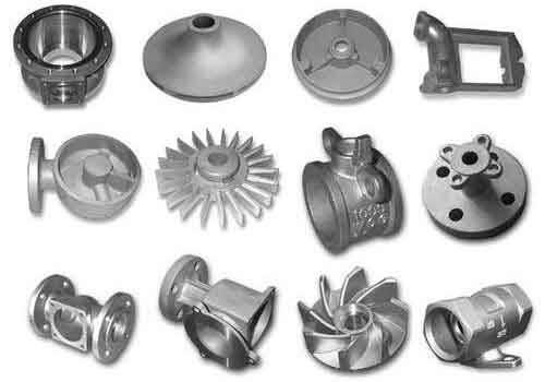
Beyond technical details, the visual inspection of sand casting parts is crucial. During assembly, I always check for surface defects and internal soundness through non-destructive testing. The image below shows an example of a well-produced sand casting part, illustrating the complexity and quality achievable with proper工艺. It serves as a reference for how optimized sand casting yields robust components for marine applications.
To further summarize the工艺 parameters for different valve shells, I have compiled Table 2, which compares key aspects across the cases. This table helps in standardizing approaches for similar sand casting parts.
| Parameter | Five-Way Valve Shell | Three-Way Valve Shell | Small Valve Shell |
|---|---|---|---|
| Casting Weight (kg) | 46 | 36 | 5 |
| Gating/Riser Weight (kg) | 27 | 30 | 5 |
| Yield (%) | 63 | 54.6 | 50 |
| Min Wall Thickness (mm) | 10 | 10 | 4 |
| Pouring Temperature (°C) | 1000-1020 | 980-1020 | 980-1000 |
| Shrinkage Allowance (%) | 1.2 (pattern), 0.8 (core) | 1.2 | 1.2 |
| Number of Cores | 2 | 1 | 2 |
| Riser Type | Top and side risers | Top and side risers | Small feeders |
| Chill Material | Graphite | Graphite | Graphite |
The use of chills is particularly important for silicon brass sand casting parts. Graphite chills are preferred due to their high thermal conductivity and ease of machining into complex shapes. The chill effectiveness can be modeled using heat transfer equations. For a chill in contact with the casting, the heat extraction rate $\dot{Q}$ is given by Fourier’s law: $$ \dot{Q} = -k \cdot A \cdot \frac{dT}{dx} $$ where $k$ is thermal conductivity, $A$ is contact area, and $\frac{dT}{dx}$ is the temperature gradient. Graphite has a $k$ value around 100-150 W/m·K, making it efficient for drawing heat from hot spots. In practice, I design chills to have a thickness of 20-30 mm for heavy sections, ensuring they do not become heat sinks that cause premature solidification in unwanted areas. This balance is key to producing sound sand casting parts.
Another aspect is the pouring practice. For silicon brass, I recommend a pouring speed that maintains a constant metal level in the sprue to avoid aspiration. The pouring time $t$ can be calculated as: $$ t = \frac{V_{\text{casting}}}{Q} $$ where $V_{\text{casting}}$ is the volume of the casting. For the five-way valve shell, with a volume of approximately 5000 cm³, and a flow rate of 500 cm³/s, the pouring time is about 10 seconds. This rapid pour helps prevent cold shuts. Additionally, degassing is less critical for silicon brass compared to aluminum alloys, but I still use inert gas flushing if the melt shows signs of gas absorption. The hydrogen solubility in silicon brass is low, reducing the risk of gas porosity in sand casting parts.
Quality control extends beyond the casting process. After shakeout, I subject sand casting parts to heat treatment if required, though ZCuZn16Si4 often does not need it due to its as-cast properties. However, stress relieving at 300°C for 2 hours can be beneficial for complex shapes to prevent distortion during machining. Machining allowances are typically 3 mm for flanges and bores, but for thin sections like grids, I add 0.75-1.5 mm of stock for grinding. This ensures final dimensions meet tight tolerances. Hydrostatic testing is the ultimate validation for valve shells. The test pressure $P$ is applied according to the formula for thin-walled pressure vessels: $$ \sigma = \frac{P \cdot r}{t} $$ where $\sigma$ is the hoop stress, $r$ is the inner radius, and $t$ is the wall thickness. For a 4.5 MPa test on a 125 mm diameter shell with 10 mm wall, $\sigma$ is about 28 MPa, well below the yield strength of silicon brass. This confirms the integrity of sand casting parts.
In conclusion, sand casting silicon brass marine valve shells requires a deep understanding of alloy behavior and process optimization. Through principles like strategic risering, gating design with filters, and judicious use of chills, defects can be minimized. The case studies demonstrate that each sand casting part demands a tailored approach, but common threads include horizontal pouring, careful core design, and controlled solidification. By emphasizing these techniques, foundries can consistently produce high-quality sand casting parts that meet stringent marine standards. The keyword ‘sand casting parts’ recurs throughout this discussion because it encapsulates the end goal: reliable components manufactured through a time-tested process. As technology advances, simulation tools can further refine these methods, but the fundamentals remain rooted in empirical knowledge and attention to detail. I hope this insights help others in producing superior sand casting parts for critical applications.
To reiterate, the success of sand casting parts like valve shells hinges on preventing defects through proper工艺. Cold shuts are avoided by fast filling, shrinkage by risers and chills, and oxides by filtration. The formulas and tables provided offer quantitative guidance, but experience is invaluable. In my foundry, we continuously monitor process variables and inspect every sand casting part to ensure consistency. This commitment to quality has enabled us to deliver thousands of defect-free valve shells, contributing to safer marine operations. As the demand for durable sand casting parts grows, sharing such knowledge becomes essential for advancing the industry.