
In modern manufacturing, the demand for complex, lightweight, and high-integrity components continues to grow. Among these, sand casting parts with thin-walled geometries present a significant challenge. Traditional pattern-making for such components, often reliant on wood, suffers from inherent limitations including susceptibility to moisture-induced warping, wear during molding, and poor durability—issues that are exacerbated in thin sections. This study explores a transformative approach by integrating Fused Deposition Modeling (FDM), a ubiquitous additive manufacturing (AM) technology, into the sand casting workflow for producing high-quality thin-wall sand casting parts. The core hypothesis is that FDM-printed patterns offer superior dimensional stability, surface finish, and longevity compared to wooden counterparts, thereby improving the overall quality and reducing the lead time for casting complex components.
Fundamental Challenges in Thin-Wall Sand Casting
The production of thin-wall sand casting parts is governed by complex interplay between fluid dynamics, heat transfer, and solidification mechanics. The primary challenges can be summarized as follows:
- Mold Filling: High surface-area-to-volume ratios lead to rapid heat loss from the molten metal, increasing viscosity and potentially causing misruns or cold shuts before the mold cavity is completely filled. The critical velocity for successful filling, $v_c$, can be related to the wall thickness, $t$, and the metal’s fluidity length, $\lambda_f$, often approximated by empirical relations such as:
$$ v_c \propto \frac{\lambda_f}{t^n} $$
where $n$ is an exponent typically greater than 1, indicating the heightened difficulty with decreasing thickness. - Pattern Integrity: Wooden patterns for thin sections are prone to mechanical damage during the ramming of sand. Repeated use leads to edge wear and dimensional inaccuracies, which are directly transferred to the mold cavity and subsequently to the final sand casting parts.
- Solidification & Stress: Thin walls solidify rapidly, which can hinder proper feeding from risers, leading to shrinkage porosity. Furthermore, constrained thermal contraction can induce high residual stresses, risking distortion or hot tearing.
The following table contrasts the traditional and FDM-based pattern-making approaches for producing thin-wall sand casting parts:
| Parameter | Traditional Wooden Pattern | FDM-Printed Pattern |
|---|---|---|
| Material | Seasoned Hardwood (e.g., Mahogany, Pine) | Engineering Thermoplastics (ABS, PLA, PETG) |
| Dimensional Stability | Low; susceptible to humidity/temperature | High; isotropic, minimal hygroscopic effect |
| Wear Resistance | Moderate; edges degrade with use | High; consistent surface over many cycles |
| Fabrication Lead Time | Weeks (manual carpentry, drying) | Hours to Days (automated printing) |
| Complex Geometry | Difficult & Costly | Easily Achieved |
| Modification Cost | High | Low (digital CAD edit & re-print) |
| Suitability for Thin-Walls | Poor | Excellent |
Integrating FDM Technology into the Casting Process
FDM operates on the principle of extruding a thermoplastic filament through a heated nozzle, depositing material layer-by-layer to build a three-dimensional object. For creating patterns for sand casting parts, this digital-to-physical process offers unparalleled flexibility. The procedural integration involves several critical stages:
1. CAD Model Preparation and Casting Simulation
The process begins with a precise 3D model of the desired final component. For a thin-wall disc-like component—a common yet challenging geometry for sand casting parts—the digital model must incorporate all necessary casting modifications. These include:
- Draft Angles: To facilitate pattern withdrawal from the sand mold.
- Shrinkage Allowance: A uniform scaling factor applied to compensate for metal contraction during solidification. For common cast steels, this is typically between 1.5% and 2.5%. The scaled dimension, $D_{pattern}$, is calculated from the desired final dimension, $D_{final}$, and the shrinkage allowance, $S$:
$$ D_{pattern} = D_{final} \times (1 + S) $$ - Machining Allowance: Additional material added to critical surfaces that will be machined post-casting.
Modern casting simulation software is then employed to virtually analyze filling, solidification, and potential defect formation. This step is crucial for optimizing the gating and risering system before any physical pattern is made, saving material and time. Key outputs from simulation inform the final pattern design, ensuring the mold will fill completely and solidify soundly, which is paramount for thin-wall sand casting parts.
2. FDM Pattern Printing: Parameters and Optimization
The success of the FDM pattern hinges on correct parameter selection to achieve a balance between surface quality, dimensional accuracy, strength, and build time. The primary parameters and their effects are summarized below:
| Parameter | Typical Range/Value | Impact on Pattern Quality |
|---|---|---|
| Layer Height | 0.1 mm – 0.3 mm | Lower height improves surface finish but increases print time. |
| Infill Density & Pattern | 30% – 50% (Grid, Triangular) | Provides internal support, prevents collapse during printing and sand ramming. |
| Wall (Perimeter) Count | 3 – 5 | Higher count increases shell strength and surface durability. |
| Printing Temperature | Material Dependent (e.g., ABS: 230-250°C) | Affects layer adhesion and melt flow; crucial for strength. |
| Build Plate Adhesion | Brim or Raft | Prevents warping and ensures first-layer stability for large, flat patterns. |
| Print Orientation | Major flat surface on build plate | Minimizes need for supports on critical surfaces, reduces stair-stepping on vertical walls. |
For a thin-wall disc pattern, orienting the major flat face (the parting plane) directly on the build plate is optimal. This orientation minimizes the notorious “stair-step” effect on critical vertical surfaces (like the disc’s rim) and provides the greatest strength against the lateral forces experienced during sand molding. A moderate layer height (e.g., 0.2 mm) offers a good compromise. A robust shell defined by 4-5 perimeters and a 40% triangular infill ensures the pattern can withstand repeated molding cycles without deflection, especially in the thin-walled sections crucial for the final sand casting parts.
3. Post-Processing and Molding
Once printed, the pattern requires minimal post-processing. Light sanding can be applied to remove any minor support material remnants or layer lines, though a slightly textured FDM surface often provides excellent grip for the parting dust applied during molding. The FDM pattern is then used in standard foundry practices. For the example disc component, a simple drag-and-cope mold or a more specialized process like cutting-back (a form of loose-piece molding) can be employed. The chemical and abrasion resistance of polymers like ABS allows the pattern to be used for dozens of molds without significant wear, a stark contrast to wooden patterns.
Results and Comparative Analysis
The implementation of FDM-printed patterns for producing thin-wall sand casting parts yields measurable benefits across multiple metrics. The dimensional fidelity of the cast component is directly linked to the pattern’s accuracy. FDM patterns, built from a stable digital file, exhibit consistent dimensions, whereas wooden patterns can vary with environmental conditions.
The surface roughness of the cast part, $R_{a,cast}$, is influenced by the pattern’s surface finish, $R_{a,pattern}$, and the sand grain fineness, $AFS$. The relationship can be conceptually modeled as a transfer function where a smoother pattern finish allows for better replication of the sand mold’s detail onto the metal:
$$ R_{a,cast} \approx f(R_{a,pattern}, AFS, \text{metal penetration}) $$
FDM patterns, when printed with fine layers and properly finished, provide a superior starting point, reducing the need for extensive post-casting finishing on the sand casting parts.
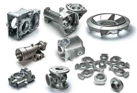
Most significantly, the problem of thin-wall incompleteness (misruns) is mitigated. A perfectly dimensionally stable FDM pattern ensures the mold cavity’s thin sections are accurately formed and maintained during molding. This, combined with a gating system optimized via prior simulation, ensures consistent, complete filling. The mechanical robustness of the plastic pattern eliminates the fear of damaging delicate thin sections during the sand-ramming process, a frequent cause of defective molds when using worn wooden patterns.
Discussion: Economic and Operational Implications
The adoption of FDM for pattern-making fundamentally alters the economics of producing low-volume or prototype sand casting parts. The digital workflow eliminates the need for skilled pattern-makers for every design iteration, reducing labor costs and dependency on specialized craftsmanship. Lead time collapses from weeks to a matter of days: a complex pattern can be designed, simulated, printed, and ready for molding within 48-72 hours.
This agility enables foundries to adopt a just-in-time pattern production model, reducing physical inventory and storage costs. It also facilitates mass customization, where variations of a base design can be produced for different clients without the prohibitive cost of multiple wooden patterns. For thin-wall sand casting parts used in aerospace, automotive, or specialized machinery, where weight reduction and structural efficiency are critical, this technology provides a rapid, cost-effective pathway from concept to functional metal component.
Conclusion and Future Outlook
This study demonstrates that FDM technology serves as a powerful enabler for advancing the sand casting of thin-walled components. By replacing traditional wooden patterns with digitally manufactured, durable plastic counterparts, significant improvements in geometric accuracy, surface finish, and production reliability for thin-wall sand casting parts are achieved. The methodology directly addresses the core failure modes of conventional pattern-making—wear, warpage, and damage to delicate features—thereby elevating the overall quality standard for complex castings.
The future of this synergy is bright. Emerging trends include the use of high-temperature resistant polymers or polymer composites for FDM patterns capable of withstanding more aggressive molding processes or higher production volumes. Furthermore, the logical progression is toward direct sand printing (binder jetting), where the sand mold is 3D printed directly from the CAD model, completely bypassing the need for a physical pattern. However, for many applications, especially where existing molding equipment and expertise are in place, FDM-patterned casting offers a perfect transitional technology—blending digital flexibility with traditional foundry robustness. This integrated approach paves the way for more agile, cost-effective, and high-quality manufacturing of intricate sand casting parts, meeting the evolving demands of modern industry.