
In my years of experience as a foundry engineer, I have encountered numerous challenges related to sand casting defect, particularly shrinkage porosity. This defect is one of the most detrimental sand casting defect types because it compromises mechanical integrity and leads to premature failure of components. In this article, I will share my practical approaches to diagnosing and eliminating shrinkage porosity, drawing from real production cases involving both ferrous and non-ferrous alloys. The discussion will emphasize how understanding the solidification sequence, mold design, and process parameters can transform a recurring sand casting defect into a manageable quality issue.
Shrinkage porosity occurs when the liquid metal contracts during solidification without adequate compensation from adjacent molten metal. This is a classic sand casting defect that manifests in thick sections, junctions, or regions near gates. I have seen it in ductile iron chain sprockets, aluminum alloy installation brackets, and hydraulic valve bodies. Each case required a tailored solution, but the underlying principles remain the same: control thermal gradients and ensure proper feeding.
Let me first describe a typical scenario I faced with aluminum alloy (ZL116) installation parts produced by metal mold casting. Although this is not a sand mold, the defect mechanisms are analogous to those in sand casting. The component was a frame-type structure with wall thickness of 4 mm and a weight of 0.85 kg. The alloy composition is given in Table 1. The original gating system was bottom-fed with two ingates and two top risers. Unfortunately, more than 70% of the first trial castings exhibited shrinkage porosity at the rib locations adjacent to the ingates.
| Element | Si | Mg | Ti | Al | Mn | Zn | Fe | Impurities Total |
|---|---|---|---|---|---|---|---|---|
| Content | 6.5–8.5 | 0.35–0.55 | 0.1–0.3 | Balance | ≤0.10 | ≤0.30 | ≤0.30 | ≤1.0 |
To understand why this sand casting defect (or its metal-mold equivalent) occurred, I analyzed the temperature distribution during pouring. The bottom-fed system caused the hottest metal to enter last, creating an inverse temperature gradient that favored last-to-freeze regions near the ingates. The ribs at those locations had no riser connection, and the thin ingates solidified early, blocking any liquid supply. This is a common root cause of shrinkage porosity, whether in sand molds or metal dies. The solution required modifying the feeding path without changing the part geometry.
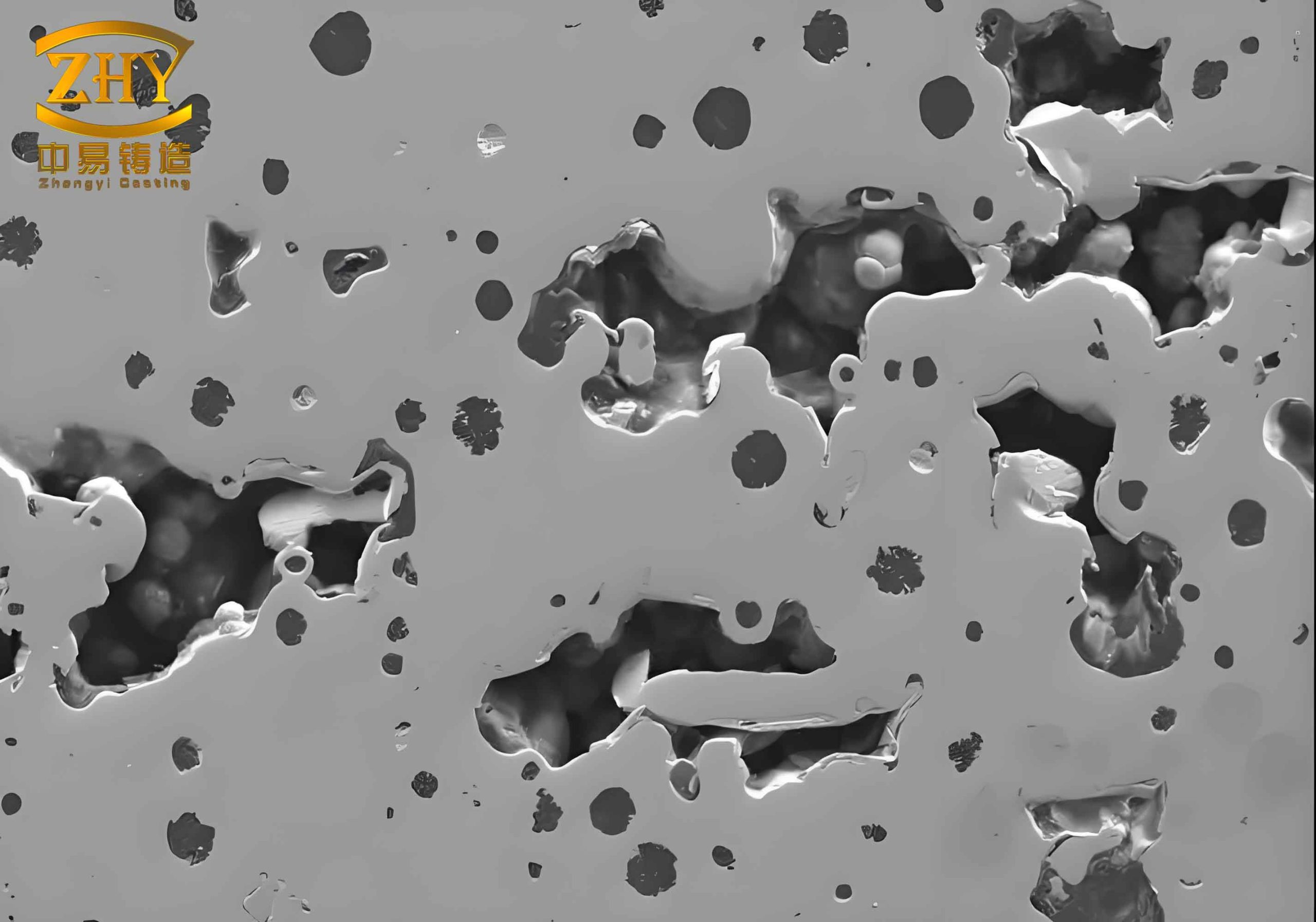
Figure 1 illustrates a typical casting with a region prone to shrinkage porosity, similar to the one I encountered.
After several unsuccessful attempts (lower pouring temperature, increasing runner height, adding blind risers), I realized the fundamental issue: the ribs had no direct contact with a molten metal reservoir. I redesigned the gating system by widening and heightening the runner, and adding four vertical slots that directly connected the runner to the two problem ribs. These slots acted as local feeders. The result was dramatic: out of 64 test castings, only one had shrinkage porosity (1.6% defect rate). In subsequent mass production of 15,000 pieces, the defect rate stabilized at 1.3%, and overall casting yield exceeded 94%. This experience reinforced my belief that most sand casting defect problems can be solved by providing directional solidification and adequate feeding.
Another case involved ductile iron chain sprockets produced in metal molds. The material was austempered ductile iron (ADI), which required a specific heat treatment. The process parameters are summarized in Table 2. The major challenge was preventing hot tears and cracks due to excessive contraction in the metal mold. I learned that early mold opening (when casting temperature was 800–950 °C) reduced shrinkage stress and minimized crack formation. Although this is not a classic sand casting defect, the principle of controlling solidification shrinkage applies universally.
| Parameter | Value |
|---|---|
| Metal mold preheat temperature | ≈300 °C |
| Coating | Acetylene black |
| Mold opening temperature (casting) | 800–950 °C |
| Quenching (austenitizing) | 890±10 °C, 60 min |
| Quenching (isothermal) | 360±10 °C, 100 min |
| Process yield | 85% |
For hydraulic valve body castings, I worked with resin sand cores to produce complex internal passages. A common sand casting defect in these parts is core bending or displacement, leading to wall thickness variation and internal leakage. I designed a frame-type core print to increase core rigidity. The details are shown in the following design concepts (not illustrated here). The frame could be either monolithic or assembled from two core parts. This approach eliminated core drift and improved dimensional accuracy of oil grooves. The defect rate due to core-related misalignment dropped from over 10% to below 2%. This demonstrates that even when the primary defect is not shrinkage, the same systematic root-cause analysis used for sand casting defect can be applied.
To quantify solidification behavior, I often use Chvorinov’s rule, which relates solidification time to the modulus of the casting:
$$
t = C \left( \frac{V}{A} \right)^2
$$
where \( t \) is solidification time, \( V \) is volume, \( A \) is surface area, and \( C \) is a constant depending on mold material and alloy. In a sand casting defect analysis, regions with high modulus (thick sections) solidify last and become hot spots. If these hot spots are not connected to a feeder, shrinkage porosity appears. The solution is to place risers or chills to equalize solidification time. For the ZL116 installation part, the modulus of the problem rib was calculated as:
$$
M_{\text{rib}} = \frac{0.004 \times 0.02}{2(0.004+0.02)} \approx 0.0018 \text{ m}
$$
Compared to the adjacent thicker sections, this rib had a lower modulus, but its location near the ingate made it a local hot spot because of prolonged hot metal flow. Therefore, the feeding design must consider flow dynamics, not just geometry.
I also apply the concept of feeding distance, which for aluminum alloys can be approximated by:
$$
L_f = k \cdot d
$$
where \( L_f \) is the maximum distance that a riser can feed, \( d \) is the section thickness, and \( k \) is a coefficient (typically 3–4 for aluminum). In the original design, the distance from the nearest riser to the defect rib exceeded \( 4d \), confirming insufficient feeding. By adding the vertical slots, I effectively reduced the feeding distance to less than \( 2d \), eliminating the sand casting defect.
Another powerful tool is the temperature gradient analysis. For a unidirectional solidification, the gradient can be expressed by Fourier’s law:
$$
q = -k \frac{dT}{dx}
$$
where \( q \) is heat flux, \( k \) is thermal conductivity, and \( dT/dx \) is temperature gradient. A steep gradient promotes directional solidification and reduces shrinkage porosity. In the metal mold process for chain sprockets, the preheated mold (300 °C) reduced the gradient sufficiently to avoid hot tears but not so low as to cause excessive shrinkage. The optimal gradient was achieved by controlling both mold temperature and coating thickness.
I have compiled a comparative table of the three cases to highlight commonalities in solving sand casting defect issues, as shown in Table 3.
| Component | Alloy | Process | Primary Defect | Root Cause | Solution | Defect Rate Before/After |
|---|---|---|---|---|---|---|
| Installation bracket | ZL116 (Al-Si-Mg) | Metal mold | Shrinkage porosity | Inverse temperature gradient, no feeding to ribs | Added vertical feeding slots from runner | 70% → 1.3% |
| Chain sprocket | ADI (ductile iron) | Metal mold | Hot cracks | Excessive contraction in rigid mold | Early mold opening (800–950 °C) | Not quantified but eliminated |
| Hydraulic valve body | Gray iron / ductile iron | Sand mold (resin cores) | Core shift / wall thickness variation | Insufficient core rigidity | Frame-type core prints | 10% → 2% |
In my experience, the most effective way to prevent a sand casting defect like shrinkage porosity is to perform a solidification simulation before tooling construction. I have used simple analytical models as well as commercial software. For example, the Niyama criterion is widely used to predict shrinkage porosity in casting simulation:
$$
N = \frac{G}{\sqrt{R}}
$$
where \( G \) is temperature gradient and \( R \) is cooling rate. A low Niyama value indicates high risk of microporosity. In the aluminum installation part, the simulated Niyama values at the rib locations were below the threshold (typically 0.1 for Al alloys), confirming the problem. After modifying the gating, the Niyama values increased to safe levels.
Another critical parameter is the feeding efficiency of risers. The modulus of a riser must be greater than that of the casting section it feeds. Mathematically:
$$
M_{\text{riser}} \geq 1.2 \, M_{\text{casting}}
$$
This rule is well-known in sand casting to avoid a sand casting defect. For the chain sprocket, the metal mold riser design followed this principle, ensuring adequate feeding despite the faster solidification in metal molds.
I also emphasize the role of melting and treatment practices. For ZL116 alloy, the presence of silicon above 6% requires modification to refine the eutectic silicon morphology. Without modification, the acicular silicon acts as stress raisers and promotes crack initiation, which can be mistaken for a sand casting defect but is actually a metallurgical defect. The modification with strontium (Sr) at 720–730 °C for 10–15 minutes, followed by degassing with argon at 700–720 °C, significantly improved the mechanical properties and reduced interdendritic shrinkage. Table 4 summarizes the melting parameters.
| Process step | Temperature (°C) | Time (min) |
|---|---|---|
| Degassing (Argon) | 700–720 | 8–15 |
| Modification (Sr addition) | 720–730 | 10–15 |
| Static holding | — | 10–15 |
| Pouring temperature | 720±10 | — |
| Melt holding time (max) | — | 360 (6 hours) |
In addition to process control, I have found that careful inspection of the first-off castings is essential. For the installation bracket, we performed radiography on the first 64 pieces. The defect location correlated precisely with the simulated hot spots. This validated our simulation model and gave confidence in the modified design. I recommend that every foundry develop a database linking simulation results to actual sand casting defect observations; this accelerates problem-solving.
One often overlooked aspect is the influence of pouring temperature. In the aluminum bracket trial, we initially lowered the pouring temperature from 720 °C to 700 °C, hoping to reduce shrinkage. However, this caused incomplete filling and cold shuts, which are also a type of sand casting defect. The proper approach was to maintain adequate superheat for fluidity while ensuring that the last-to-freeze regions remained connected to feeders. The solution of adding vertical slots allowed us to keep a safe pouring temperature (720 °C) without creating defects.
The hydraulic valve body case taught me that sand casting defect prevention starts with core design. The conventional method of simply extending core prints did not provide enough support for long, slender cores. By designing a frame-type core print that connected the core to the mold at multiple points, we increased the effective bending stiffness. The core deflection under ferrostatic pressure was reduced by a factor of 3, as estimated by:
$$
\delta = \frac{P L^4}{8 E I}
$$
where \( \delta \) is deflection, \( P \) is pressure, \( L \) is unsupported length, \( E \) is modulus of elasticity, and \( I \) is moment of inertia. By reducing \( L \) via additional supports, deflection decreased dramatically. This is a perfect example of how mechanical design can eliminate what appears to be a sand casting defect.
To further illustrate the impact of controlled solidification, I developed a simple heat balance for the metal mold casting of the chain sprocket. The heat extracted by the mold during solidification is:
$$
Q = m \, (c_p \Delta T + L_f)
$$
where \( m \) is mass, \( c_p \) is specific heat, \( \Delta T \) is temperature drop, and \( L_f \) is latent heat. For a 1 kg sprocket, with \( c_p \approx 700 \) J/(kg·K), \( \Delta T \approx 1000 \) K (from pouring temperature ~1400 °C to solidus ~1150 °C), and \( L_f \approx 272 \) kJ/kg, the total heat is about 1.0 MJ. The mold preheat at 300 °C reduces the thermal shock and allows a more uniform heat extraction, minimizing the thermal gradient that causes hot tears—another manifestation of a sand casting defect in ductile iron.
I would like to share a systematic approach I use for tackling any sand casting defect, which I call the “4-D Method”: Define, Diagnose, Design, and Deliver.
- Define the defect: location, frequency, morphology (e.g., localized shrinkage, dispersed porosity, cracks).
- Diagnose root cause: use simulation, temperature measurement, modulus calculation, and literature.
- Design modifications: gating/risering changes, mold/core design, process parameter adjustments.
- Deliver validation: produce trials, inspect, and iteratively refine until defect rate is acceptable.
This method has worked for me across various alloys and processes. Table 5 shows a typical checklist I follow when a new sand casting defect appears.
| Checkpoint | Possible Indication | Action |
|---|---|---|
| Is the defect in a heavy section? | Insufficient riser size | Increase riser modulus |
| Is the defect near the ingate? | Hot spot from flowing metal | Add chill or relocate ingate |
| Is the defect dispersed? | Low thermal gradient | Increase mold temperature or add exothermic material |
| Is the defect associated with a core? | Gas evolution or core collapse | Improve core venting or core strength |
| Is the alloy prone to microporosity? | Long freezing range | Modify composition or use grain refinement |
One final case worth mentioning is the production of thin-walled iron castings in green sand. I encountered a persistent sand casting defect where shrinkage appeared along the centerline of a 6 mm plate. The modulus of the plate was 3 mm, and the riser modulus was 3.5 mm, which should have been sufficient. However, the green sand moisture content was too high, causing a rapid heat extraction at the mold surface that reversed the thermal gradient. By reducing mold moisture from 4.5% to 3.8%, the defect disappeared. This underscores that sand casting defect analysis must consider mold material properties as well.
In conclusion, my journey with shrinkage porosity and other sand casting defect issues has taught me that there is no single magic bullet. Each defect demands a thorough understanding of heat transfer, fluid flow, and solidification metallurgy. By applying principles such as Chvorinov’s rule, modulus calculations, and feeding distance theory, and by systematically modifying gating, risering, and process parameters, I have been able to reduce defect rates from unacceptable levels to below 2% in most cases. The key is to treat every sand casting defect as an opportunity to deepen your knowledge of the casting process. I hope that my experiences, shared here, will help other engineers in their own quest to produce sound castings.