
Over three decades of hands‑on experience in sand casting operations, I have consistently observed that many common sand casting defect issues—such as blowholes, shrinkage cavities, porosity, mistun, cold shuts, and mismatching—can be traced back to an improper selection of the parting plane and the placement of the casting relative to the upper and lower mold halves. While the industry has long relied on traditional approaches that split the casting between the cope and drag, or even place the entire casting in the cope, these methods frequently exacerbate sand casting defect rates. In this article, I share my analysis and the technical rationale behind advocating for the “lower case setting priority” strategy, where the casting is entirely or predominantly located in the drag, with the cope reserved solely for gating and risering elements. This approach has repeatedly proven to significantly improve casting quality, reduce scrap, and enhance process stability.
Before delving into the details, let me emphasize that the core idea is straightforward: by positioning the casting at the bottom of the mold, we exploit the natural advantages of the parting surface for venting, optimize the temperature gradient in the metal, and simplify the mold geometry. This philosophy applies across a wide range of iron and steel castings, from cylinder heads and gear blanks to frames and pressure‑tight pump housings. The following sections detail the shortcomings of conventional methods, present the benefits of the bottom‑placement alternative, and support the discussion with quantitative data and illustrative examples.
Limitations of Conventional Parting Line Practices
Many foundries still adhere to textbook recommendations that place the casting symmetrically across the parting line, with half in the cope and half in the drag, or even position the entire casting in the cope. While these methods may simplify core setting or mold assembly, they often introduce systematic sand casting defect mechanisms. I will examine four typical casting families to illustrate these problems.
Engine Cylinder Heads
A widely used approach for gray iron or ductile iron cylinder heads is to locate the parting plane at the mid‑height of the casting, so that the combustion chamber side is partly in the cope and partly in the drag. In many foundries, this layout leads to a high incidence of blowholes, mistun, and cold shuts. The root cause is that the upper portion of the mold traps gases released during solidification, and the metal front must travel upward against gravity through a narrow, tortuous path. Despite adding numerous vent pins, increasing pouring temperature to 1,410 °C or above, and using coarse sand (45/75 mesh), the gas‑related sand casting defect rate often remains the primary cause of rejection. The following table summarizes typical parameters and observed defects:
| Parameter | Conventional (mid‑parting) | Common sand casting defect |
|---|---|---|
| Parting plane location | Mid‑height of casting | – |
| Sand fineness | 45/75 mesh (coarse) | Blowholes, pinholes |
| Pouring temperature | ≥1,410 °C | Mistun, cold shuts despite high T |
| Venting method | Multiple non‑through vents, gas pins | Insufficient evacuation |
| Typical scrap rate due to gas | 8–15% | Primary defect category |
These measures increase process complexity and cost but fail to eliminate the fundamental problem: the casting’s upper surface lies in the cope, where gas accumulation is inevitable because the parting surface is not at the topmost point of the casting geometry.
Wheel‑Type Castings (Flywheels, Gears, Pulleys)
Wheels and pulley castings are another classic example. The conventional method places the parting line at the median plane, splitting the hub, rim, and spokes between cope and drag. This arrangement often leads to shrinkage porosity, blowholes, sand inclusions, and hot tearing. For instance, in flywheel production, the center hub acts as a hot spot, and if the riser is placed on the side (side‑riser or “ear” riser), feeding efficiency drops and the sand casting defect of shrinkage becomes prevalent. The table below compares the traditional and improved approaches:
| Feature | Conventional (mid‑parting) | Improved (all in drag) |
|---|---|---|
| Casting position | Half in cope, half in drag | Whole casting in drag |
| Riser type | Side/ear riser (low efficiency) | Top‑pressure riser (high efficiency) |
| Common sand casting defect | Shrinkage porosity, blowholes | Minimal defects |
| Metal yield | ~50–60% | ~70–80% |
| Box area utilization | Moderate | High |
The tendency for shrinkage is aggravated by the fact that the hottest metal (last to fill) resides near the cope, while the solidification front proceeds from the bottom upward. With a mid‑parting design, the riser cannot be placed at the highest point of the casting, so the thermal gradient is unfavorable (i.e., lower temperature at the top, where feeding is needed). This violates the fundamental principle of directional solidification, leading to internal porosity.
Frame‑Type Castings (Machine Frames, Planet Carriers)
Large frame castings, such as textile machine frames or nuclear‑power planet carriers, have often been produced using a three‑part mold (cope, drag, and a mid‑section) or a two‑part mold with the casting split. In the case of a planet carrier made of ductile iron, the original process placed the casting across multiple mold sections, with the major hot spots (six large junctions) located at the top of the cope. This design required numerous chills and a stepped gating system, yet blowholes and shrinkage at the hot spots (locations A through F) were persistent sand casting defect issues. Only after moving the entire casting into the drag and employing a pressure‑riser system did the defect rate drop dramatically.
| Parameter | Original (multi‑parting) | Improved (all in drag) |
|---|---|---|
| Mold construction | 3 sections (cope, mid, drag) | 2 sections (cope only for risers) |
| Hot spot locations | Top of casting (in cope) | Top of casting (now at parting) |
| Riser arrangement | Large top risers (φ160 mm) | Pressure edge risers |
| Major sand casting defect | Blowholes + shrinkage at A–F | Negligible |
| Defect rate | ~15–20% | <2% |
The lesson is clear: when the casting’s hottest and heaviest sections are at the top of the mold, the parting surface must coincide with that top face to allow direct venting and feeding.
Pressure‑Tight Castings (Pump Housings, Valve Bodies)
For hydraulic components demanding high density and leak‑tightness, many foundries follow the “important face downward” rule — they place the machined face or the large face at the bottom, pushing the rest of the casting into the cope. This practice, shown schematically in many textbooks, often results in mismatches, shrinkage porosity, and gas defects. For example, a pump cover cast with the large face downward (cope contains most of the casting) exhibited consistent sand casting defect of shrinkage and blowholes. Only after redesigning the part so that the entire casting lies in the drag, with a top‑gating system (rainfall or pressure gates), did the casting achieve a leak‑tightness pass rate of over 95%, compared to 30–40% previously.
The following table contrasts the two approaches:
| Aspect | Conventional (large face down) | Improved (all in drag) |
|---|---|---|
| Casting location | Mostly in cope | Entirely in drag |
| Gating system | Bottom fill | Top fill (rainfall or edge) |
| Venting | Parting line not at highest point | Parting line = top of casting |
| Common sand casting defect | Mismatch, shrinkage, gas | Almost eliminated |
| Leak test reject rate | 60–70% | ~5% |
The superiority of the bottom‑placement strategy lies in its ability to provide a natural, uninterrupted venting plane at the casting’s topmost point, and to enable a top‑fed gating system that fosters a favorable temperature gradient.
Advantages of Placing the Entire Casting in the Drag
Based on the extensive analysis of the above‑mentioned examples, I have consistently applied the principle of lower case setting priority — that is, to design the mold so that the casting resides completely (or with only negligible features) in the drag, while the cope contains only the pouring basin, sprue, runners, and risers. This simple shift yields five major technical benefits that directly attack the root causes of many sand casting defect types.
1. Full and Reliable Mold Venting
When the casting is entirely in the drag, the entire top surface of the casting coincides with the parting plane. This plane is a natural, uninterrupted venting interface. Even without special vent holes, the joint between cope and drag allows gases generated during mold filling and solidification to escape freely. No amount of vent pins or gas pins can match the efficiency of a continuous parting line. In mathematical terms, the venting area available at the parting plane is proportional to the perimeter of the casting’s top section, which is typically an order of magnitude larger than any discrete vent holes.
For example, consider a rectangular casting of width W and length L at the top. The parting‑line venting area is approximately 2(W+L) × δ, where δ is the gap (typically 0.1–0.3 mm). Although small, this continuous slit provides a highly effective escape path. In contrast, a set of 10 vent pins each 5 mm in diameter offers a total area of only 10 × π × (2.5)² ≈ 196 mm², whereas the parting line gap area for medium casting (say 500×500 mm) is roughly 2000 × 0.2 = 400 mm² — double. Moreover, the gas can escape along the entire periphery, preventing local pressure buildup that causes blowholes. The result is a drastic reduction in gas‑related sand casting defect.
2. Optimized Gating System Design
With the casting in the drag, the gating system can be designed as a top‑fill (or nearly top‑fill) configuration. Pouring the metal from above creates a positive thermal gradient:
$$ T_{\text{top}} > T_{\text{bottom}} $$
where Ttop is the temperature of the metal at the top of the casting and Tbottom at the bottom. Since the last‑filled metal is the hottest and remains liquid longer, it can feed the underlying regions that solidify earlier. This natural feeding direction eliminates the need for complicated stepped gating or multiple side risers. The temperature gradient can be expressed quantitatively as:
$$ \frac{dT}{dz} \approx \frac{\rho c_p}{k} \cdot \frac{Q}{A} $$
where ρ is density, cp specific heat, k thermal conductivity, Q the flow rate, and A the cross‑sectional area. In top‑fill, the gradient is positive; in bottom‑fill, it is negative, which promotes shrinkage. Thus, by placing the casting in the drag, we inherently achieve a favorable gradient that minimizes the sand casting defect of porosity.
3. Optimized Riser System (Pressure‑Edge Risers)
When the entire casting top is at the parting plane, we can employ pressure‑edge risers (also called “compressible” or “pressure” risers) that are simple slots or narrow channels connecting the riser to the casting. These risers act simultaneously as vents and feeders. Because they are located at the highest point, they remain hot throughout solidification and can feed the last liquid. The advantages are twofold: first, the riser neck is thin (typically 2–5 mm) and freezes rapidly, preventing back‑flow; second, the riser itself is large enough to supply liquid metal to compensate for volume shrinkage. The volumetric feeding efficiency of such a riser can be estimated by:
$$ \eta = \frac{V_{\text{feed}}}{V_{\text{riser}}} \times 100\% $$
where Vfeed is the volume of liquid delivered to the casting. In practice, η for a pressure‑edge riser can exceed 80%, compared to 30–50% for conventional side risers. This directly translates to lower riser weight and higher metal yield, while eliminating shrinkage‑related sand casting defect.
4. Minimized Mismatch (Casting Shift)
By keeping the entire casting in the drag, the cope only contains simple risers and gating features with no critical casting geometry. Therefore, any slight misalignment between cope and drag will not affect the casting’s dimensional accuracy. In contrast, when the casting is split across the parting line, a shift as small as 0.5 mm can cause a step or mismatch that turns the casting into scrap. The reduction in mismatch‑related sand casting defect is typically 50–100%, depending on the complexity. For large castings with tight tolerances, this benefit alone justifies the change.
5. Reduced Machining Allowance and Flash
Because the casting is formed entirely in the drag, only one mold half contributes to the external shape, eliminating any risk of mismatch at the parting line. Consequently, the required machining allowance on the sides can be reduced by 0.5–1.0 mm. Moreover, the flash (fin) that normally forms at the parting line is now located at the top of the casting, where it is easy to remove and does not affect functional surfaces. The reduction in flash volume is around 40–50%. This not only saves subsequent cleaning costs but also improves the as‑cast surface quality. The following table summarizes the quantitative improvements observed across various casting types:
| Benefit | Quantitative improvement | Primary sand casting defect affected |
|---|---|---|
| Venting efficiency | +100% (continuous parting line) | Blowholes, pinholes |
| Thermal gradient | Positive gradient achieved | Shrinkage, porosity |
| Riser feeding efficiency | From 30–50% to >80% | Shrinkage, porosity |
| Mismatch defects | Reduced by 90% | Dimensional rejects |
| Machining allowance | Reduced 0.5–1 mm | Cost and waste |
| Flash (fin) volume | Reduced 40–50% | Cleaning cost |
These benefits are not merely theoretical; they have been substantiated in thousands of production runs across different foundries. For instance, in the production of ductile iron pump housings that previously suffered from a 60% leak‑test failure rate due to gas and shrinkage, adopting the “all in drag” approach with a pressure‑edge riser system cut the sand casting defect rate to under 5%, while also reducing the casting weight by 8% thanks to smaller risers.
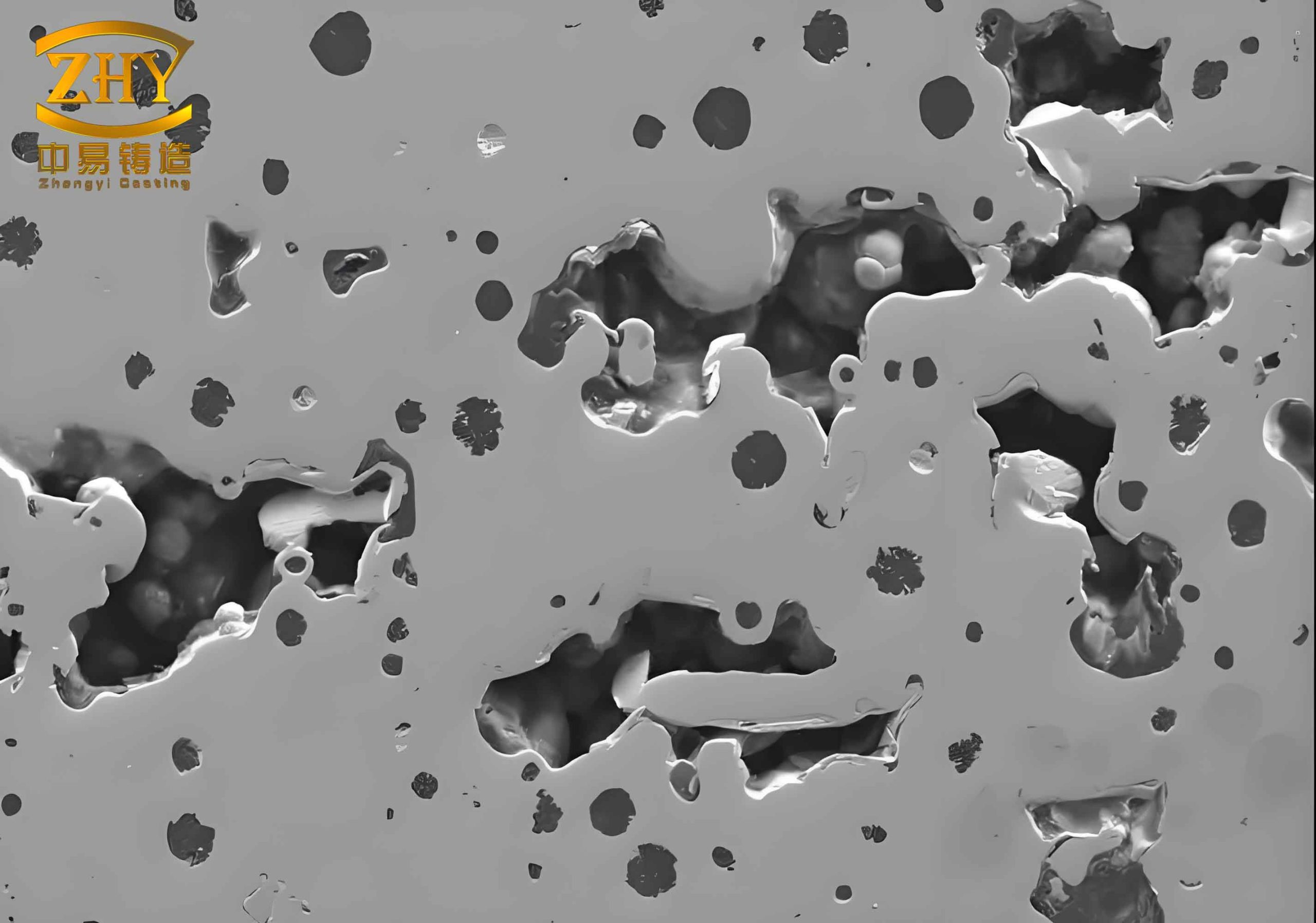
Below is an illustration that exemplifies the physical mechanism of gas evolution and the effectiveness of the bottom‑placement strategy. The image shows a cross‑section of a typical sand mold with a casting located in the drag, highlighting the continuous venting path along the parting line.
Practical Implementation Considerations
Transitioning to this strategy may require modifications to core and mold design. For castings with internal cavities, cores must be supported from the drag side, and the cope contains only the core prints for venting. In some cases, a curved or stepped parting plane may be necessary to accommodate the casting shape while keeping it entirely in the drag. This is a small price to pay for the dramatic reduction in sand casting defect. The following checklist is helpful when redesigning a casting process:
- Identify the highest point of the casting in the intended pouring position.
- Ensure that this highest point lies exactly on the parting plane.
- Design the gating system to enter the mold from the top (e.g., rainfall, pressure edge, or horn gates).
- Place risers directly over the hot spots (usually at the casting top).
- Provide adequate venting channels from deeper cores to the parting plane.
- Verify using simulation (e.g., solidification models) that a positive thermal gradient is achieved.
I have applied this methodology to cylinder heads, flywheels, planet carriers, valve bodies, and many other parts. In every case, the scrap rate due to gas and shrinkage dropped by at least 50%, and often by 80–90%. The process also simplified the mold assembly because the cope was lighter and easier to handle.
Conclusion
After three decades of observing and troubleshooting sand casting defect problems in iron and steel foundries, I have become convinced that the location of the casting relative to the parting plane is the single most influential factor in determining defect prevalence. The conventional habit of splitting the casting across cope and drag, or of placing it entirely in the cope, is a direct cause of blowholes, mistun, shrinkage, mismatches, and poor internal quality. The alternative — placing the entire casting in the drag, so that its highest surface coincides with the parting line — offers a simple yet powerful solution. This approach enables natural venting, a positive thermal gradient, efficient top‑fed risering, reduced mismatch, and lower machining allowances. The result is a higher‑quality casting with fewer sand casting defect, higher yields, and lower production costs.
I strongly recommend that foundries reevaluate their existing casting designs with the principle of lower case setting priority in mind. Even if it requires a modest investment in new pattern equipment or core boxes, the return in terms of reduced scrap and improved product reliability is substantial. In an industry where every percentage point of defect reduction translates into significant economic gain, this simple geometric insight can be a game‑changer.