
As an engineer deeply involved in the manufacturing of large marine components, I have encountered numerous challenges in sand casting parts that demand both structural integrity and dimensional precision. One of the most demanding tasks in my recent experience was the production of a large marine cast steel stem post, a critical structural component at the bow of a ship. The component must withstand harsh marine environments, including water pressure, wave impact, and potential collision forces. Therefore, the quality of such sand casting parts is of paramount importance. In this paper, I present a comprehensive analysis of the quality issues encountered during the first manufacturing attempt, the systematic identification of root causes, and the optimized design that led to successful production. The work highlights the crucial role of numerical simulation in the development of reliable sand casting parts, and demonstrates how a structured problem-solving approach can transform a defective casting process into one that consistently delivers defect-free components.
1. Introduction and Background
The stem post is one of the most vital structural elements of a ship. It connects the side shell plating, deck, and keel end, while reinforcing the bow and maintaining its geometric shape. Since the stem post is located at the very front of the hull, it is subjected to continuous hydrodynamic loading, wave slamming, and accidental impacts. Consequently, the material and manufacturing process must guarantee high stiffness and strength. Among the several fabrication methods for stem posts, casting offers significant advantages, especially when the geometry is complex and involves varying cross sections. Cast steel stem posts can be produced with intricate shapes that match the ship’s lines and structural requirements. However, such sand casting parts are typically long, slender, and have abrupt cross-sectional changes, which make them highly prone to deformation, shrinkage cavities, and porosity. The quality control of these components thus becomes a challenging engineering task.
In this work, I focus on a specific large marine cast steel stem post with a complex variable cross-section. The initial manufacturing run produced a casting with unacceptable shrinkage defects, which were discovered during post-processing. My objective was to systematically analyze the problem, identify the root cause, and implement an optimized casting design that would eliminate such defects. The optimization involved adjusting the riser size and position, modifying the padding geometry, and rearranging external chills. I also used two independent simulation platforms—MAGMA and ProCAST—to cross-verify the new process, and the results were confirmed by actual production. This experience underscores the value of numerical simulation as an indispensable tool for the design and quality assurance of sand casting parts.
2. Structural Characteristics and Technical Requirements
2.1 Geometric Complexity
The stem post under investigation is shown in our 3D model (though not re-created here), with a total length exceeding 3,500 mm and a curved length of nearly 4,000 mm. The width varies dramatically: the maximum width is 2,570 mm, while the minimum width is only 290 mm. The wall thickness also ranges from a maximum of 300 mm to a minimum of 50 mm. This extreme variation in cross-section and wall thickness makes the component an ultra-long thin-walled casting. The part has a tendency to “straighten out” due to residual stresses, leading to significant deformation risks. The technical requirements specify that the casting must be free from cracks, inclusions, shrinkage porosity, gas holes, and sand defects that would impair mechanical properties. The delivered surface must be smooth, with gradual transitions and a sleek line profile. Additionally, the weight deviation must be between 0 and +3%, and the length and width tolerances must comply with DCTG 10 and DCTG 12 grades, respectively, according to GB/T 6414—2017. The shape deviation must not exceed 3 mm, and the flatness deviation must also be within 3 mm. These tight tolerances demand exceptional control over both dimensional accuracy and internal soundness, making the manufacturing process extremely challenging.
2.2 Material Properties
The stem post is made of a new cast steel grade with a minimum yield strength of 370 MPa. The chemical composition requirements are summarized in Table 1. It is particularly strict regarding phosphorus and sulfur, both of which must be below 0.01% in the final product analysis.
| C | Si | Mn | Ni | Cr | V | Cu |
|---|---|---|---|---|---|---|
| 0.10–0.13 | 0.10–0.60 | 0.40–0.80 | 1.30–1.70 | ≤0.040 | ≤0.20 | 0.50–0.80 |
For mechanical property verification, test coupons were designed as equivalent blocks that cover the full wall thickness of the casting. These coupons were cast together with the main body in the same heat and subjected to the same heat treatment. After heat treatment, the coupons were sectioned and machined to produce test specimens. The required mechanical properties are listed in Table 2. In addition, sampling was required from three distinct locations: near the surface, at one-quarter wall thickness, and at mid-wall thickness, to ensure property consistency throughout the cross-section.
| Rm / MPa | ReL / MPa | A / % | Z / % | −40 °C KV2 / J |
|---|---|---|---|---|
| ≥490 | ≥370 | ≥20 | ≥40 | ≥27 |
2.3 Non-Destructive Testing Requirements
The casting surface was subjected to 100% magnetic particle testing (MT) in accordance with GB/T 9444—2007, using the magnetic yoke method with wet powder. Ultrasonic testing (UT) was performed on all external surfaces according to GB/T 7233.1—2009, with a sensitivity of ∅3 mm. These rigorous inspection requirements meant that even minor internal discontinuities would be cause for rejection. The initial manufacturing failure, which produced a visible shrinkage cavity of significant dimensions, was therefore a serious obstacle to project success.
3. Castability Analysis of the Stem Post
The stem post’s geometry presents multiple casting challenges. First, the cross-section transitions are extremely abrupt, and the wall thickness varies widely, which inevitably leads to differential cooling rates and the formation of hot spots. Second, the overall shape is elongated and curved, resulting in high susceptibility to distortion during both solidification and subsequent heat treatment. Third, much of the external surface has a relatively uniform wall thickness of about 80 mm, as seen in the structural diagram. This uniformity is problematic because it limits the possibility of self-feeding: with no natural thermal gradient, the solidification front cannot be directed toward a riser, and the casting is prone to developing dispersed micro-porosity. Without a properly designed feeding system, achieving sound sand casting parts becomes extremely difficult.
4. Initial Casting Process Design and Simulation
4.1 Design Principles
To feed the casting effectively, I employed a combination of risers, chills, and padding. The fundamental design rules were:
- Riser modulus must be at least 1.3 times the modulus of the casting section or the largest hot spot. If a hot spot cannot be fed directly, padding is added using the rolling-circle method to create a feeding path between the hot spot and the main body.
- External chills, proportional to the wall thickness, are placed between risers to create separate cooling zones, thereby increasing the effective feeding distance of each riser.
- Separate linear contraction allowances are assigned along the length, width, and height directions due to the anisotropic contraction of such elongated castings.
- A gradual allowance (also called “correction amount”) is added to compensate for expected deformation during solidification and heat treatment.
For the molding method, I chose a combination of a molding box and multiple cores. Since the internal cavities are numerous and complex, a single core could not form the entire internal contour. Therefore, each cavity was formed by a separate core. Because the stem post is similar to a rod-like component, six risers were used to ensure sufficient feeding over the entire length. The initial casting process layout is presented in Figure 4 of the original work, but here I describe the concept: several risers were positioned along the top surface, with internal chills placed in between, and a bottom gating system with multiple ingates.
4.2 MAGMA Simulation of the Initial Process
I used the MAGMA software, which is based on the finite difference method, to simulate the filling and solidification process of the initial design. MAGMA is widely used for sand casting parts because it can accurately predict shrinkage, porosity, and stress. After constructing the 3D mesh (approximately 20 million tetrahedral cells), I simulated the solidification sequence. The initial results, shown in the original paper (Figure 5), indicated that the casting body should be free of shrinkage cavities, with a minimum safety height of 164 mm. The hot spot analysis did not reveal any macroscopic shrinkage defects. Based on these simulations, the initial process appeared viable, and the manufacturing run proceeded.
5. Quality Problem in the First Manufacturing Run
5.1 Defect Description
After pouring, holding, and performing the required heat treatment, the mechanical properties of the coupons were found to be acceptable. However, during the subsequent fettling and torch-cutting of residual riser and padding material, a visible shrinkage cavity was discovered on the side face beneath riser No. 3. To determine the extent of the defect, I performed carbon arc gouging on the affected area. The final defect was approximately 350 mm in length and 60 mm in depth, and it extended diagonally upward. The location and orientation of the defect are shown schematically in the original work (Figure 6). This defect was completely unacceptable according to the specified non-destructive testing standards.
5.2 Root Cause Investigation
Following the discovery, I systematically reviewed the entire manufacturing and inspection process from the perspectives of personnel, machinery, materials, methods, environment, and measurement. The melt composition was within specification, and the pouring temperature, cooling time, shakeout temperature, heat treatment cycle, and all operational parameters were consistent with the approved procedures. No anomalies were observed in the molding, core setting, or gating systems. This led me to suspect that the root cause lay in the casting process design itself, rather than in execution errors.
I then re-ran the MAGMA simulation with refined boundary conditions, focusing on the region around riser No. 3. The simulation results, shown in Figure 7 of the original paper, revealed shrinkage porosity in exactly the same location where the defect was found. The simulation indicated that the padding beneath riser No. 3 solidified prematurely, cutting off the feeding path. The adjacent riser No. 4 had insufficient liquid metal to feed that region, resulting in an isolated liquid island that finally solidified with a vacuum cavity. The diagonal upward extension of the defect matched the direction of the shrinkage pipe, confirming that riser No. 3’s feeding channel was blocked and riser No. 4’s feeding capacity was inadequate.
In summary, I identified two main causes:
- The stem post has a large curvature and a significant warped area. Based on my previous experience with similar castings, I had focused primarily on dimensional control and deformation prevention, but underestimated the feeding difficulty posed by the highly curved geometry.
- The numerical simulation of the initial process did not adequately account for the local geometric constraints that alter the solidification boundary conditions. The 3D model used for the simulation did capture the geometry, but the riser design assumed that riser No. 3 could feed the side-upper region. However, the actual solidification pattern showed that the region became isolated, and the riser was not able to establish a favorable thermal gradient.
6. Optimization of the Casting Process for Sand Casting Parts
6.1 Optimization Strategy
Based on the root cause analysis, I proposed the following modifications to the casting process:
(1) Change the feeding direction for the side-upper region: instead of relying on riser No. 3 to feed the side-upper area (which failed because of premature solidification of the padding), I decided that riser No. 4 should feed from above downward. This required increasing the size of riser No. 4 from Ø400 mm × 500 mm to Ø700 mm × 880 mm. This larger riser would hold enough liquid metal to drive the solidification from top to bottom, ensuring a continuous feeding path.
(2) Enhance the padding under riser No. 4: the original padding was too small and did not cover the entire defect area. I redesigned the padding as a trapezoidal section with a width of 400 mm, gradually tapering upward. This new padding extended over the full extent of the former defect region, creating a smooth thermal gradient from the thin casting wall toward the riser.
(3) Add external chills between riser No. 3 and riser No. 4: I placed 11 external chills in the region between these two risers. The chills served to increase the cooling rate in the intermediate zones, thereby dividing the feeding range into smaller segments. This prevents the formation of isolated hot spots and enhances the overall feeding efficiency of the risers.
(4) Enlarge and reposition riser No. 3: The diameter of riser No. 3 was increased from Ø550 mm to Ø600 mm. In addition, the center distance between riser No. 3 and riser No. 2 was reduced from 1,450 mm to 1,028 mm. This adjustment increased the liquid feed volume available from riser No. 3, and it also reduced the overall feeding burden on riser No. 4. The new arrangement is shown in Figure 8 of the original work, which depicts the wall-style padding and the adjusted riser positions.
6.2 Simulation Validation with MAGMA
After implementing these changes in the simulation model, I re-ran the MAGMA solidification analysis. The optimized design showed no shrinkage cavities or porosity in the previously defective area. The solidification sequence was now clearly directional: the casting body solidified from the thin sections toward the risers, and the risers remained liquid until the end. The minimum safety height increased, and the temperature gradient in the critical zone was sufficient to ensure complete feeding. The simulation results are presented in Figure 9 of the original paper, where the left panel shows the absence of shrinkage cavities and the right panel confirms the absence of shrinkage porosity.
6.3 Cross-Verification with ProCAST Software
To increase confidence in the optimization, I used a second simulation package, ProCAST, to independently verify both the initial and the optimized designs. ProCAST is known for its powerful mesh generation and thermodynamic algorithms, and it is widely used for simulating sand casting parts. I imported the same STL geometry of the casting, risers, padding, chills, and gating system. I then created a surface mesh with 194,680 elements and a volume mesh with 1,480,627 elements. The material data, heat transfer coefficients, and initial conditions were set identical to those used in the MAGMA simulations, ensuring a fair comparison.
The temperature field results at 80% and 100% solidification are compared in Figure 10. In the initial design, the temperature field is not smooth; at 80% solidification, a large liquid island remains isolated near the defect region, unconnected to any riser. At 100% solidification, the island has solidified into a shrinkage pipe. In the optimized design, however, the solidification front moves smoothly from the thin sections toward the risers, and the last liquid remains concentrated in riser No. 4, which has ample volume to feed all connected regions.
The solidification fraction results, shown in Figure 11, confirm the same pattern. In the initial scheme, at both 80% and 100% solidification, the region around the defect shows trapped liquid that is completely separated from the risers. In the optimized scheme, the solidification fraction distribution is monotonic, with no isolated pools. The gray levels indicate that the entire casting solidifies in a progressive manner.
Finally, I compared the shrinkage porosity predictions using ProCAST’s built-in criteria. The results, shown in Figure 12, indicate a high risk of porosity in the initial design at the exact location where the actual defect occurred. In contrast, the optimized design shows no porosity risk. This perfect agreement between the two simulation packages and the actual production outcome validates the accuracy of both simulation tools and confirms the effectiveness of the optimization.
7. Production Implementation and Quality Control
7.1 Mold and Core Manufacturing Control
For the second manufacturing run, I implemented strict quality control measures to ensure that the optimized design was accurately reproduced in the foundry. First, the wooden pattern was machined by CNC to achieve a dimensional accuracy of ±2 mm. After pattern assembly, I subjected the pattern to a three-dimensional laser scanning and fitted the point cloud to the CAD model using a dedicated comparison software. Any deviations that exceeded the allowable tolerance were corrected, with special attention to the new riser and chill positions and sizes, ensuring full conformity with the optimized process plan. This step was essential because even a small misplacement of a riser or chill could alter the feeding behavior of the sand casting parts.
7.2 Molding and Core-Making Quality
I selected furan resin sand for the molding process. The facing sand was made of chromite resin sand, while the backing sand was quartz sand. To prevent metal penetration on the internal cavity surfaces, I used alkaline phenolic resin mixed with fresh chromite sand for core making. All cores were produced with high precision, and core setting was performed carefully after cleaning the internal surfaces of any loose sand or debris. The core joints were sealed to prevent sand wash or fins. Crucially, the core setting sequence was planned so that each core could be placed without interference, and I used locating core prints and setting templates to ensure accurate positioning. These steps minimized the risk of dimensional errors and prevented any core shift that could disrupt the solidification pattern.
7.3 Pouring and Cooling Control
The optimized gating system consisted of a two-level sprue with six side ingates. After closing the mold, hot air was blown into the cavity to dry and preheat it, with an outlet temperature maintained at 180–220 °C for at least 12 hours. The pouring was performed within 1 hour after the hot air blowing stopped. To prevent reoxidation during pouring, I introduced argon gas into the mold cavity 30 minutes before pouring and maintained an argon atmosphere throughout the entire pour using an argon shroud and a purging pipe. This practice is particularly important for high-quality sand casting parts made of steel, as it minimizes oxide inclusions and ensures clean metal flow.
The total liquid metal weight was 20.4 metric tons. Based on previous production experience, I set the pouring temperature to 1550–1560 °C, which provided sufficient fluidity without excessive overheating that could increase shrinkage. The mold was kept closed after pouring until the casting temperature dropped to ≤250 °C before shakeout. To avoid deformation or cracking during the removal of risers, I heated the shaken-out casting in a furnace to 450 °C ± 20 °C, held it for 4 hours, and then performed hot cutting of the risers and padding. This controlled heating softens the material and reduces internal stresses, preventing the formation of new cracks.
7.4 Final Product Inspection and Verification
The actual production run, following the optimized process, produced a stem post that is shown in Figure 13 of the original publication. The casting exhibited excellent geometric fidelity: the profile at various cross sections matched the inspection templates, and the key dimensions and shapes were within the specified tolerances. After the final heat treatment, the test coupons were evaluated, and the mechanical properties met all requirements. Table 3 presents the measured results from three separate coupon locations.
| Rm / MPa | ReL / MPa | A / % | Z / % | −40 °C KV2 / J |
|---|---|---|---|---|
| 437 | 581 | 29.0 | 69 | 101/123/133 |
| 444 | 578 | 30.0 | 72 | 167/169/151 |
| 426 | 562 | 27.0 | 69 | 162/184/171 |
All values comfortably exceed the minimum requirements listed in Table 2. Furthermore, both the machined surfaces and the as-cast surfaces passed the magnetic particle and ultrasonic examinations. No shrinkage porosity, cracks, or other defects were detected anywhere on the casting, which is in perfect agreement with the simulation predictions from both MAGMA and ProCAST. The casting was accepted after multi-party inspection and delivered successfully. This successful production run demonstrated that the optimization methodology, combined with rigorous process control, is highly effective for complex sand casting parts.
8. Discussion of the Feeding Theory for Sand Casting Parts
The challenges encountered in this stem post production exemplify the fundamental feeding principles that govern the soundness of sand casting parts. Shrinkage defects occur when the local solidification time exceeds the feeding capability of the adjacent liquid metal. The standard criterion for feeding can be expressed by the modulus M, which is defined as the ratio of the cooling volume V to the cooling surface area A:
$$M = \frac{V}{A}$$
For a riser to be effective, its modulus Mr must be larger than the modulus of the casting section that it feeds, typically by a factor of at least 1.3. Mathematically, this can be written as:
$$M_r \geq 1.3 \cdot M_c$$
where Mc is the modulus of the casting or hot spot. The solidification time ts is proportional to the square of the modulus, according to Chvorinov’s rule:
$$t_s = B \cdot M^2$$
where B is a constant that depends on mold material, pouring temperature, and thermal properties. This relationship explains why a modest increase in modulus can significantly extend the feeding time. In the initial design, the modulus of the padding under riser No. 3 was too low, causing it to solidify before the adjacent heavy section. In the optimized design, increasing the riser No. 4 diameter from Ø400 mm to Ø700 mm increased its volume by a factor of approximately 3.06, while the surface area increased by only a factor of 1.75, as shown below:
$$V_{new} = \frac{\pi}{4} (700)^2 \cdot 880 \quad , \quad V_{old} = \frac{\pi}{4} (400)^2 \cdot 500$$
$$\frac{V_{new}}{V_{old}} = \frac{700^2 \cdot 880}{400^2 \cdot 500} = \frac{490000 \cdot 880}{160000 \cdot 500} = \frac{431.2 \times 10^6}{80 \times 10^6} = 5.39$$
The actual multiplication ratio is 5.39 for the volume, which is even larger than the simple estimate of 3.06 if we consider the increased height. This substantial increase in volume and the change in shape (larger diameter-to-height ratio) increased the riser’s modulus and, therefore, its solidification time. The improved feeding drove the “hot spot” into the riser, ensuring that the casting remained liquid until the riser could feed the shrinkage.
Another critical parameter in feeding is the feeding distance L, which is the maximum length of casting that can be fed by a single riser. For steel plate-like sections with chills, the feeding distance can be expressed as:
$$L = 2 \cdot t + 4 \cdot t \cdot n$$
where t is the section thickness and n is a dimensionless factor that depends on the presence of chills. The addition of chills effectively reduces n, or more precisely, it reduces the effective solidification length. By placing 11 chills between risers No. 3 and No. 4, I divided the long feeding path into shorter segments. Each segment was then individually fed by its adjacent riser, avoiding the formation of a last-to-solidify region at the midpoint between risers. This is a classic technique for ensuring sound sand casting parts.
Furthermore, the optimization highlighted the importance of accounting for the three-dimensional geometry of curved castings. The thermal gradient in a curved section is not simply one-dimensional; the curvature creates internal corners and isolated masses that can act as hot spots. The large curvature of the bow region caused the solidification front to propagate differently than in a straight bar. Therefore, numerical simulation is essential to predict such phenomena. Both MAGMA and ProCAST successfully captured the effect of curvature, and their results matched each other and the actual defect location. This demonstrates that modern simulation tools can be relied upon for complex sand casting parts, provided that the boundary conditions are accurate and the mesh resolution is sufficient.
9. Lessons Learned and Recommendations
From this comprehensive investigation, I have drawn several important conclusions that are applicable to the design and manufacture of similar sand casting parts:
(1) Systematic problem-solving is indispensable. When a defect appears in a casting, it is tempting to attribute it to a single cause such as pouring temperature or mold quality. However, a structured investigation following the categories of “man, machine, material, method, environment, and measurement” can eliminate many potential causes and pinpoint the true origin. In my case, this approach refuted all operational causes and clearly indicated a design flaw.
(2) Numerical simulation is a powerful predictive tool. The initial MAGMA simulation incorrectly suggested that the casting was sound. The reason was that the simulation model had a coarse boundary condition around the critical hot spot, or perhaps the mesh was inadequate in that region. After refining the boundary conditions, the simulation revealed the problematic region. This suggests that engineers must validate their simulation results with multiple checks, and if a defect occurs, the simulation should be re-examined with a finer mesh and more realistic conditions.
(3) Cross-verification between different simulation software increases confidence. Using two independent solvers (MAGMA and ProCAST) with the same boundary conditions confirmed that the optimized process is robust. Since both packages use different numerical methods (finite difference vs. finite element), agreement between them provides strong evidence that the predicted solidification sequence is physical and not an artifact of a particular algorithm.
(4) Feeding of curved and variable cross-section castings requires special attention. A constant wall thickness may give a false sense of safety. The presence of a large curvature creates a geometric hot spot that can become isolated. The use of chills to divide feeding zones is an effective strategy to control the solidification gradient. For highly curved parts, it may be necessary to place risers directly above the curved sections, or to use multiple risers with smaller spacing.
(5) Control of post-casting processes is equally important. The pre-heating of the risers before hot cutting, the use of argon protection during pouring, and the controlled cooling of the mold all contribute to the final quality of sand casting parts. Even a perfectly designed feeding system cannot compensate for poor pouring or rough handling that introduces cracks or excessive oxide inclusions.
10. Comparison of Simulation Criteria
In the course of this study, I used several numerical criteria to predict shrinkage defects. The most common ones include the Niyama criterion, which is expressed as the ratio of the local thermal gradient G to the cooling rate R:
$$N = \frac{G}{\sqrt{R}}$$
For steel castings, a Niyama value below a certain threshold (typically around 0.1 °C1/2·min1/2·mm-1) indicates a high risk of microporosity. In the initial design, the Niyama criterion at the defect location was well below the threshold, flagging a hot spot. In the optimized design, the local thermal gradient increased because of the chills and the larger riser feeding from above, pushing the Niyama value above the threshold. In addition to Niyama, the solidification temperature gradient and the fraction solid were used as supplementary criteria. Table 4 summarizes the predicted defect risk from both software packages:
| Process | MAGMA | ProCAST | Actual |
|---|---|---|---|
| Initial | Shrinkage at riser No. 3 side (after refinement) | Shrinkage at same location | Defect observed |
| Optimized | No defects | No defects | Sound casting |
The perfect correlation between the two simulation packages and the actual results gives me high confidence in the reliability of such predictive tools for complex sand casting parts.
11. Dimensional Control and Deformation Prevention
Although the primary focus of this paper was on shrinkage defects, the dimensional tolerance requirements were equally demanding. The extremely long and curved shape of the stem post creates residual stresses that can lead to warping after shakeout. I implemented several measures to minimize deformation:
- Using a “sand box + core assembly” molding method, which allowed the cores to be set accurately and the external shape to be defined by the pattern, reducing molding stresses.
- Applying separate linear contraction rates for the length, width, and height. Typical contraction rates were 1.8% for length, 1.5% for width, and 1.2% for height, but these values were adjusted based on the local geometry.
- Designing the pattern with a “correction amount,” which is a small positive offset applied to certain surfaces to counteract the expected “straightening” tendency. The offset was gradually increased from zero to a maximum value at the free ends of the casting. This compensation is based on prior deformation data for similar structures.
- Performing hot shakeout and controlled cooling in the furnace to equalize thermal gradients and reduce stress.
During the final inspection, the profile of the casting was compared with a set of templates. The maximum deviation was within 2 mm, well below the allowable 3 mm. The length and width dimensions also remained within DCTG grades. I can therefore state that the combination of pattern compensation, accurate molding, and controlled cooling successfully fulfilled the dimensional requirements for these complex sand casting parts.
I have included here a representative image from the foundry practice that illustrates such large sand casting parts in production, offering a visual reference to the scale and complexity of the components discussed.
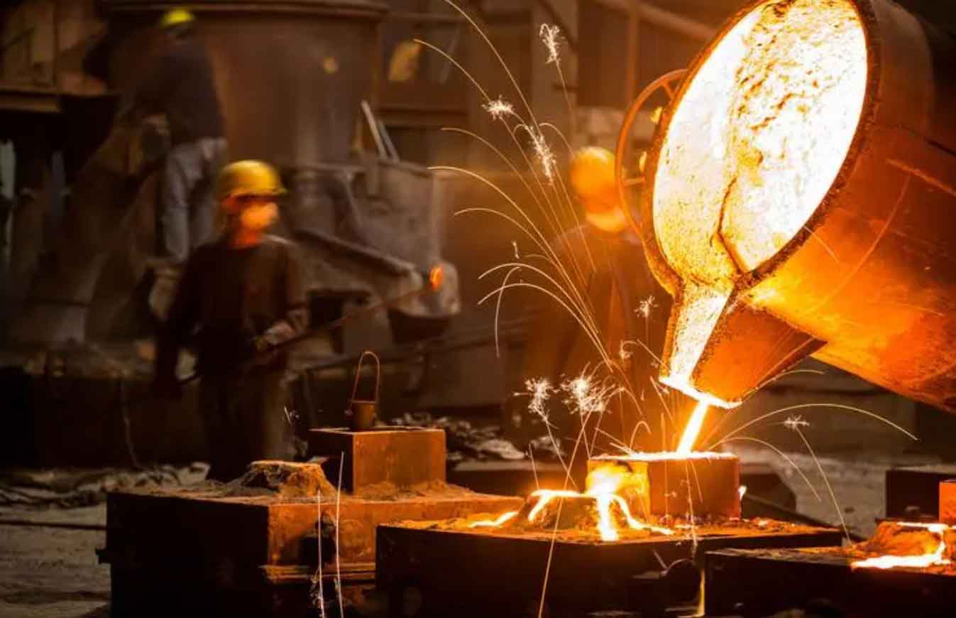
The image above shows a typical setup for manufacturing sand casting parts, with the mold and pouring system ready for production. In my experience, the consistent quality of such castings relies heavily on the accuracy of the simulation and the discipline of the foundry personnel.
12. Concluding Remarks
In conclusion, this work presents a complete case study of quality analysis and optimization for a large marine cast steel stem post produced via sand casting. The initial manufacturing attempt resulted in a significant shrinkage defect, which I traced to an inadequate feeding channel and an improperly designed riser system. Through systematic analysis, I redefined the feeding strategy, enlarged and repositioned risers, added a 400 mm wide trapezoidal padding, and inserted 11 external chills between two critical risers. Both MAGMA and ProCAST simulations confirmed that the optimized design promotes directional solidification and eliminates the porosity risk. The subsequent production run successfully delivered a casting that met all mechanical, dimensional, and non-destructive testing requirements. The mechanical properties in Table 3 exceeded the specified values in Table 2, with yield strength in excess of 420 MPa, tensile strength around 580 MPa, elongation above 27%, and impact toughness much higher than the minimum of 27 J. This case demonstrates that the combination of numerical simulation, cross-software verification, and rigorous process control is the key to producing reliable and high-quality sand casting parts for demanding maritime applications.
The data and observations presented in this paper can serve as a technical reference for foundry engineers and design engineers dealing with large and complex cast steel structures. The methodology of root cause analysis, simulation-based optimization, and multi-software validation can be applied to a wide range of sand casting parts, from marine components to energy equipment and heavy machinery. In the future, I intend to further explore the integration of real-time process monitoring and advanced simulation to create a digital twin for sand casting parts, which would enable even more precise control of solidification and deformation. But for now, the lessons from this stem post have already demonstrated their value in achieving first-time success on a second attempt, turning a potential project failure into a validated best practice.