
Large shell-type mechanical components—machine-tool beds, wind-turbine gearbox housings, compressor casings, and similar structures—combine large overall dimensions with complex internal cavities, multiple mounting faces, and strongly varying wall thickness. These features make dimensional accuracy a functional issue rather than a cosmetic one. Misalignment of flanges, hole-position errors, or out-of-plane distortion can complicate assembly, increase machining allowance, and in severe cases affect service safety. The manufacturing problem is therefore to preserve structural integrity while holding critical dimensions over a part that may be more than a metre long and weigh around a tonne.
Lost foam casting is attractive for this class of part because the pattern is consumed by the pouring metal, eliminating the need for a sand core and a parting plane. Complex thin-wall passages and integrated ribbing can be formed in one piece, and the number of process steps is reduced. The same characteristics, however, make dimensional control sensitive to pattern behaviour, coating performance, sand support, vacuum level, pouring temperature, and solidification shrinkage. Accuracy is not obtained by tightening a single parameter; it depends on how these factors interact across a large, non-uniform casting.
Process Characteristics and Precision Requirements
In lost foam casting, a polymer pattern that matches the required casting geometry is assembled into a cluster, coated with a refractory layer, dried, and embedded in dry silica sand. Vibration compacts the sand around the coated pattern, and the mold is then poured under vacuum. The liquid metal vaporizes the polymer ahead of the advancing front, and the gas escapes through the coating and the sand. After cooling, the sand is removed and the casting is cleaned and inspected. The process avoids draft angles and core-related mismatch, but the pattern is a temporary, low-stiffness body whose deformation before and during pouring can be transferred directly to the casting.
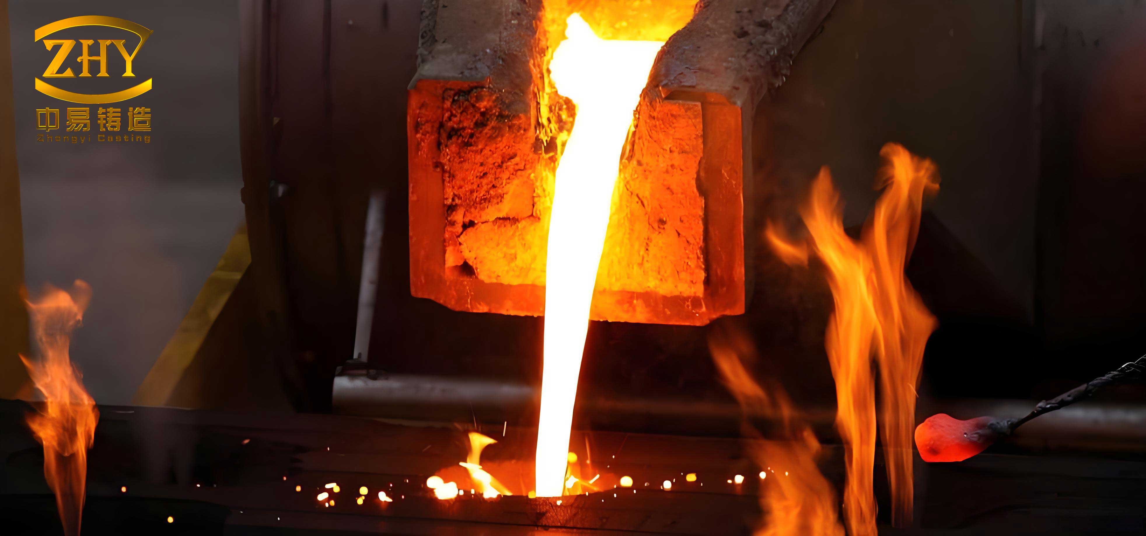
For large shell castings, typical single-piece lengths range from about 1,000 mm to 4,000 mm. Wall sections may vary from roughly 10 mm in thin ribs to 80 mm in heavy flanges or bosses. This thickness contrast creates non-uniform cooling and a tendency toward local shrinkage porosity, hot tearing, or distortion. Common accuracy targets for such parts include flange flatness within 0.3 mm/m, hole-spacing deviation within ±0.5 mm, and bore coaxiality within 0.1 mm. These are demanding values for a process in which the mold cavity is created by a pyrolyzing pattern rather than by a rigid metal die.
Sources of Dimensional Error
Pattern shrinkage and foam behaviour. Expandable polystyrene and modified polystyrene foams used for patterns typically have densities between 18 kg/m³ and 30 kg/m³. During pattern production, expansion and subsequent contraction can produce linear dimensional errors of 0.3% to 0.5%. Moisture uptake and uneven ageing can release internal stress, causing local collapse or shape change. Under the thermal load of the pouring metal, the pattern softens, shrinks, and gasifies. If the compensation allowance, venting path, or internal support is poorly arranged, local mismatch of 2 mm to 3 mm can develop. Thin walls and large flat areas are especially sensitive to softening and spring-back, and the resulting errors accumulate over the length of a large housing.
Coating drying and mold deformation. The refractory coating shrinks linearly by about 0.1% to 0.3% as solvent is removed. Uneven drying or poor ventilation can cause curling or cracking at corners and internal cavities. In multilayer coatings, different drying rates between layers can create surface-tension differences, leading to local blistering or coating detachment and a change in the effective pattern contour. Mold stiffness depends on sand compaction density and uniformity. Insufficient sand-box support or uneven vacuum extraction can allow small pattern rotations or sand displacement. In large shell components, severe cases have been associated with plane offsets of up to 12 mm, affecting flange flatness and overall symmetry.
Solidification shrinkage. Gray iron has a linear solidification shrinkage of about 0.8% to 1.0%, while ductile iron can reach about 1.3%. Rapid local cooling can generate internal contraction stresses and produce edge curling or depressions in thin sections. Thick sections cool more slowly and may develop shrinkage porosity, causing local surface sinking or dimensional collapse. An unbalanced gating system can produce asynchronous temperature fields at opposite ends of a large housing, so one side contracts more than the other and the part distorts or twists.
Process-parameter fluctuation. A vacuum level in the range of −0.03 MPa to −0.06 MPa generally provides stable mold support. Fluctuations beyond about ±0.01 MPa change the supporting force on the cavity and can cause pattern deformation or incomplete vaporization. At the reported sensitivity, a 10 °C rise in pouring temperature can advance pattern vaporization by roughly 0.1 s, enlarging fillet transitions and increasing external dimensions; too low a temperature reduces fluidity and leaves corners incompletely filled. Insufficient vibration compaction gives non-uniform sand stress and promotes shrinkage depressions or distortion on long edges. Vibration frequency is normally kept between 40 Hz and 60 Hz, outside which sand-bed stability and overall form quality can deteriorate.
Control Strategy for Large Shell Castings
Pattern design and stiffness. Pattern design must account for self-weight, thermal contraction compensation, and joint deformation. For housings longer than 2,000 mm, an internal metal skeleton or reinforcing ribs can limit sagging and thermal distortion of large faces. Shrinkage compensation should be differentiated by region: a nominal linear allowance of 1.0% to 1.2% is common, with 1.1% to 1.2% used for the shell-type housing described here, and an additional 0.2% to 0.3% overcompensation at local ribs and thin-wall transitions. The overall bending stiffness of a pattern can be estimated from:
$$K=\frac{3EI}{L^3}$$
where E is the elastic modulus of the foam, I is the second moment of area of the pattern section, and L is the free span. High-density rigid polyurethane foam has an elastic modulus of roughly 15 MPa to 30 MPa, while high-density polystyrene foam is around 2 MPa to 5 MPa, depending on density and manufacturing route. Because stiffness falls with the cube of span, increasing section depth or adding local supports is more effective than a uniform increase in foam density.
Coating and drying. The coating slurry is commonly controlled at about 70 Baumé, corresponding to a solids content of roughly 55% to 60%. This range gives suitable viscosity for uniform coverage while avoiding sedimentation at low concentration and run-off at high concentration. Refractory filler particle size is kept between about 20 µm and 50 µm to form a dense layer with adequate permeability. Coating thickness is generally 0.5 mm to 1.2 mm, applied in three to five successive layers. Drying can begin at 25 °C to 30 °C for about 48 h, followed by infrared or hot-air drying below 60 °C. The linear drying shrinkage can be estimated from:
$$\varepsilon=\frac{L_0-L_d}{L_0}\times 100\%$$
where L0 is the initial length and Ld is the length after drying. Shrinkage should be held below 0.2%; higher values increase the risk of cavity deformation. Coating thickness is a trade-off: a thicker, stiffer shell improves dimensional stability, but excessive thickness impedes gas escape and can cause gas defects or incomplete filling.
Pouring temperature, vacuum, and filling rate. For cast iron, a pouring temperature of 1,370 °C to 1,420 °C is about 150 °C to 200 °C above the liquidus range of 1,140 °C to 1,200 °C. This provides sufficient fluidity while limiting excessive pattern vaporization. Aluminum alloys are poured at 700 °C to 730 °C, roughly 70 °C to 120 °C above their 580 °C to 630 °C liquidus range. A pouring rate of about 1.5 kg/s to 2.5 kg/s is adjusted according to section volume and pattern stability. Vacuum is maintained between −0.04 MPa and −0.06 MPa to remove vaporization products rapidly and reduce the chance of gas porosity or dimensional drift caused by metal impinging on the pattern wall. Two-channel synchronized pouring or insulating wraps can reduce asymmetric contraction. Because the dried coating is hygroscopic, pouring should be completed within 48 h after drying.
Simulation and feedback. A finite-element model can couple the thermal-stress field with the flow field, including pattern ablation, metal filling, and solidification shrinkage. Inputs include the pattern vaporization curve, coating thermal conductivity—typically 0.2 W/(m·K) to 0.6 W/(m·K)—and temperature-dependent metal properties. The calculated dimensional offset can be used to correct the pattern before cutting. A conceptual deviation function can be written as:
$$\Delta L=f(T,V,\varepsilon_s,P)$$
where ΔL is the dimensional deviation, T is metal temperature, V is filling velocity, εs is pattern shrinkage ratio, and P is the vacuum level. Such a function is useful for organizing the main sensitivities, but it is not a substitute for calibration against measured castings.
Trial Configuration and Measurement
A production trial on a large compressor housing used a pattern measuring approximately 1,200 mm × 820 mm × 800 mm, with wall thickness from 18 mm to 60 mm and a casting mass of about 1 t. The pattern material was expandable polystyrene at a density of 22 kg/m³. The trial matrix included three nominal pouring-temperature groups at 1,450 °C, 1,500 °C, and 1,550 °C, each repeated more than three times. Reported comparisons also include lower pouring temperatures of 1,380 °C, 1,400 °C, and 1,420 °C combined with vacuum levels of −0.03 MPa, −0.045 MPa, and −0.06 MPa and coating stacks of three, four, and five layers.
Patterns were coated in multiple layers and dried with steam at about 50 °C for at least 48 h. They were then embedded in a silica-sand flask and compacted under vacuum vibration at 40 Hz, 45 Hz, and 40 Hz. Pouring was performed with a stepped gating system, and a thermocouple monitored the metal temperature with an error of about ±5 °C. In-mold cooling exceeded 8 h before shakeout. Dimensional inspection used a three-dimensional laser scanning system, with critical features rechecked by a coordinate measuring machine capable of ±0.02 mm accuracy. Twelve positions were measured, including shell diagonals, the four corners of the flange plane, the height centreline, and locating-hole centres. Three samples were measured per group and averaged.
Reported Parameter Effects
The reported comparison shows a consistent reduction in deviation as pouring temperature, vacuum level, and coating thickness are increased together. The selected results are summarized in Table 1. Because the three parameters change simultaneously across these rows, the table demonstrates the performance of the combined condition rather than isolating the effect of any single variable.
| Pouring temperature (°C) | Vacuum (MPa) | Coating layers | Flange flatness error (mm) | Shell height deviation (mm) | Hole-spacing error (mm) |
|---|---|---|---|---|---|
| 1,380 | −0.030 | 3 | 0.92 | +2.44 | −1.35 |
| 1,400 | −0.045 | 4 | 0.58 | +1.67 | −0.84 |
| 1,420 | −0.060 | 5 | 0.36 | +0.89 | −0.42 |
The direction of the change is technically consistent with the process mechanisms. Raising the pouring temperature from 1,380 °C to 1,420 °C reduced the shell-height deviation from +2.44 mm to +0.89 mm, indicating improved filling and less incomplete vaporization-related dimensional expansion. Increasing vacuum from −0.03 MPa to −0.06 MPa reduced flange flatness error from 0.92 mm to 0.36 mm, consistent with firmer mold support and faster removal of pyrolysis products. Adding coating layers increased cavity stiffness and reduced hole-spacing error from −1.35 mm to −0.42 mm, although excessively thick coatings can restrict gas escape.
The highest pouring temperatures are not automatically the best condition. At 1,450 °C to 1,550 °C, improved filling of complex sections must be balanced against premature pattern ablation, especially when vacuum is low or the coating is thin. Under those conditions, local collapse can occur before the metal front has established a stable cavity. The practical window is therefore a coupled one: sufficient superheat for filling, sufficient vacuum for gas removal, and sufficient coating stiffness without excessive gas resistance.
After comprehensive parameter optimization, the key dimensions of the compressor housing were held within ±1 mm. This result should be read as the outcome of the combined control package, not as a universal guarantee for all large lost foam castings. The same table shows that non-optimized combinations produced height and hole-spacing deviations well outside that band. The value of the approach lies in reducing error accumulation across pattern preparation, coating, sand support, pouring, and solidification, and in using measured castings to recalibrate the pattern and process window.
Engineering Implications
For large shell-type lost foam castings, dimensional accuracy is best treated as a chain of allowances rather than a single tolerance. The pattern must be stiff enough to resist handling and thermal softening, and its shrinkage compensation must vary by region rather than follow one global percentage. The coating must be thick enough to stabilize the cavity but permeable enough to let pyrolysis gas escape. The vacuum must support the sand without collapsing the pattern or causing excessive metal penetration. The pouring temperature and filling rate must provide superheat without advancing pattern degradation beyond the gas-removal capacity of the coating.
The compressor-housing trial illustrates the achievable direction of travel: a 1 t shell with 18 mm to 60 mm walls, a 22 kg/m³ polystyrene pattern, and a multi-layer coating was brought to key-dimension deviations within ±1 mm after coupled adjustment of temperature, vacuum, coating thickness, and pattern compensation. The result is relevant to other large housings where machining allowance is limited and flange alignment is critical. It also shows why process control in lost foam castings cannot be reduced to a single set-point. The stable solution is a calibrated window, supported by simulation, measured data, and repeated production checks.