1. Simulation analysis of liquid metal filling process
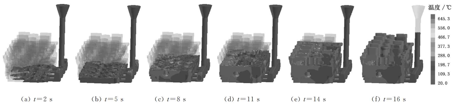
The filling state and temperature distribution at different stages of liquid metal filling process are shown in Figure 1. It can be seen that the single side bottom pouring system can realize the smooth filling of liquid metal. When t = 2S, the molten metal begins to fill the mold, as shown in Fig. 1A; When t = 5S, the filling is completed by 15%, as shown in Fig. 1b; When t = 8s, the filling is completed by 40%, as shown in Fig. 1C; When t = 11S, the filling is completed by 70%, as shown in Fig. 1D; When t = 16S, mold filling ends, as shown in Fig. 1F. The slow filling at the initial stage avoids sand flushing and air entrainment; In the last stage, due to the existence of gravity and molten metal pouring pressure, the mold filling speed slows down again, but the mold filling at the riser can be completed in the end without increasing the height of the horizontal static head.
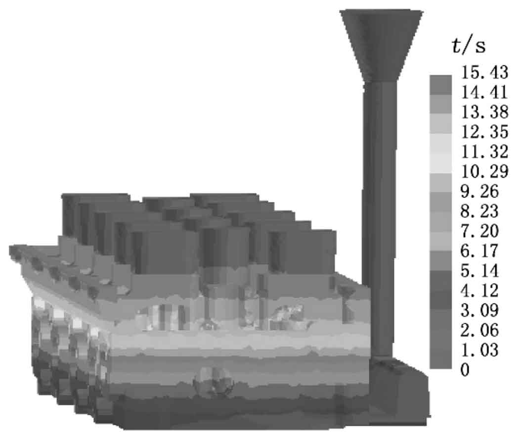
Figure 2 shows the simulation of filling time of each part of rapid sand casting. It can be seen that the whole filling process lasted 15.43s. Due to the bottom pouring method, when the filling is completed by 15%, the filling time at each filling position on the same horizontal plane is basically the same, and the filling is very stable, which can effectively avoid defects such as inclusion, turbulence and metal oxidation.
2. Simulation analysis of liquid metal solidification process
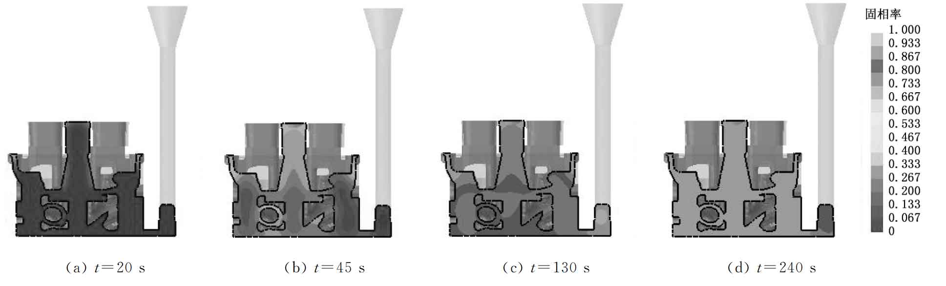
Figure 3 shows the solid rate of rapid sand casting at different solidification times. It can be seen that the outer wall of the cylinder head solidifies first, followed by the internal solidification of the rapid sand casting, and the solidification time of the gating system is the longest. The riser feeds the thick part of the upper part of the cylinder head well, and the inner sprue realizes the feeding of the thick part of the lower end of the cylinder head. There is no obvious isolated liquid phase region in the whole rapid sand casting.
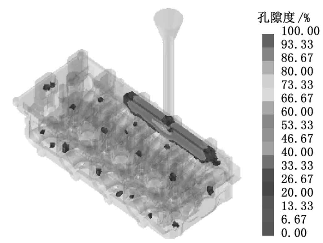
Because the liquid metal solidifies in the thin wall of rapid sand casting before the thick wall, the feeding in the liquid phase area is blocked, and shrinkage cavities and porosity are easy to form in these places. Fig. 4 shows the position and porosity of shrinkage cavity and porosity formed under this filling condition. It can be seen that there are only uniformly dispersed shrinkage cavities and porosity in the rapid sand casting, and the porosity is less than 10%, indicating that the quality of the rapid sand casting is good.
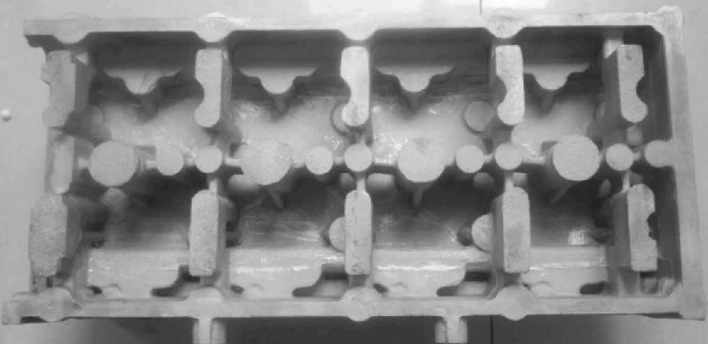
3.Production verification
According to the process design and numerical simulation results of rapid sand mold casting, the processes of molding, mold repair, coating and casting pouring are completed. See Fig. 5 for quick sand casting products of cylinder head. It can be seen that the surface contour of rapid sand casting is clear and there are no obvious defects. The location of defects in rapid sand mold casting was cut and the microstructure was observed. It was found that the structure was dense and the grain was fine.