
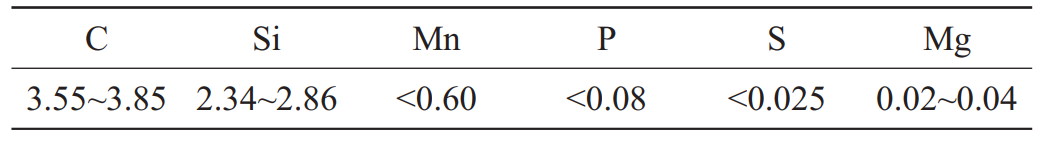
The spiral case is made of QT500-7, and its chemical composition is shown in the table. The production nature of sand castings is single piece and small batch production.
1. Sand casting process scheme
Sand casting belongs to large uneven wall thickness parts. According to the determined production program, sand casting process is adopted for production. Hand molding with furan resin self hardening sand; Use alcohol based coating to brush the surface of sand mold and sand core to form a fire-resistant protective layer on the surface, and fill the pores on the surface of sand mold and sand core. The cracks, holes, corners and uneven positions of sand mold or sand core shall be repaired with sealant, and then silver graphite powder shall be sprayed to facilitate demoulding.
2. Determination of parting surface of sand casting
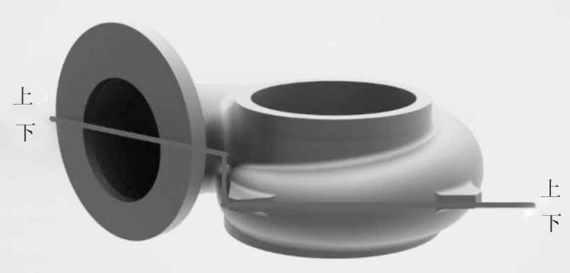
By analyzing the structure of sand casting, two boxes of stepped surface parting are adopted, as shown in Figure 1. The axial line at the inlet of the flange of the sand mold casting is not on the same plane as the spiral case pipe and the four lugs on the pipe, and the overall spiral case pipe shows a decreasing trend. In order to facilitate molding and taking parts, a stepped surface parting is set between the maximum interface of the flange and the height center of the lug to ensure that the mold is disposed from the maximum plane of the sand mold casting, which is easy to shape, easy to mold, and easy to locate the sand core, Convenient for sand removal.
3. Design of pouring system for sand mold casting
The gating system selected in the volute process design parameters is an open intermediate injection gating system. The gating system has stable liquid metal filling, low impact on the sand core, less liquid metal oxidation and strong slag retaining capacity. It is suitable for the pouring of large and medium-sized sand castings. According to the volute material, it is determined that the gate cup is made of refractory brick.
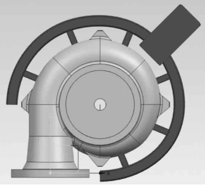
The section ratio design method is used to calculate the dimensions of each gating system of the sand mold casting. The closed gating system is selected. According to the section ratio f internal ∶ f transverse ∶ f straight = 1.0 ∶ 2.0 ∶ 1.5, the mid injection gating system is adopted, and 6 internal sprues are set. The transverse sprues are circularly distributed at the maximum section of the volute shell contour, and there are 60mm flow channels at both ends of the transverse sprue to prevent the backflow of liquid metal at the front end, It has the functions of slag collection and mold filling. According to the calculation, the cross-sectional areas of each part are respectively f resistance = 73.86 cm2, f transverse = 147.8 cm2 and f straight = 110.8 cm2. According to the calculated data, it is determined that the sprue height in the gating system is 650 mm, the upper end diameter D1 = 60 mm and the lower end diameter D2 = 55 mm; The cross-sectional area of the runner is trapezoidal, with the upper end width L1 = 94 mm, the lower end L2 = 112 mm and the height of 144 mm; The internal sprue is a flat internal sprue, with an upper width of L1 = 62 mm, a lower width of L2 = 70 mm and a height of 68 mm; According to the calculated size, the diameter of sprue nest is d = 118 mm and the height is 288 mm. A foam ceramic filter is placed at the junction between the runner and the runner to reduce the possibility of further oxidation of the metal after filtration. After completion of the design, the gating system is shown in Figure 2.
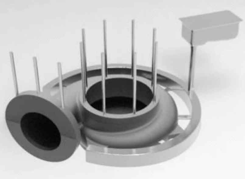
If riser feeding is used for sand castings, the process yield will be low. Therefore, combined with the material of sand castings, considering that the graphitization expansion volume of nodular iron castings will increase accordingly, the gating system with multiple internal sprues is selected to make all parts of sand castings cool and solidify synchronously according to gravity as far as possible. The liquid volume shrinkage can be moderately reduced after the pouring temperature is moderately reduced. According to the above characteristics, the sand mold casting of spiral case is carried out in the form of pouring without riser and 8 air outlets with a diameter of 30 mm, so as to discharge the gas in the middle mold cavity. The location of air outlet is shown in Figure 3.