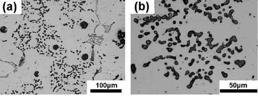
The as-cast microstructure of high nickel ductile iron observed under a microscope is shown in the figure.The graphite spheroidization of high nickel ductile iron is lower than that of high silicon molybdenum ductile iron. There are about 2-4 graphites per 100um x 100um area.Most graphite is mainly spherical, with some polygonal or special graphite appearing occasionally. The diameter of graphite is usually 5-25um, which distributes at the matrix and grain boundary.Many scholars have studied the relationship between graphite size, carbon equivalent (CE) and the number of spherical graphite. It is generally believed that the number of spherical graphite increases with the increase of carbon equivalent in any section.
According to the calculation, the carbon equivalent of high silicon molybdenum ductile iron and high nickel ductile iron are 4.67 and 3.93 respectively. The carbon equivalent of high silicon molybdenum ductile iron is 16% higher than that of high nickel ductile iron. Therefore, the graphite ductility of high silicon molybdenum ductile iron is relatively higher than that of high nickel ductile iron.
CE=C+Si/3+P/5
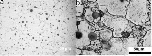
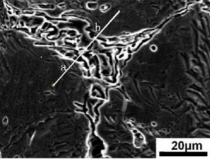
The microstructure of high nickel ductile iron consists mainly of white matrix, spherical or nearly spherical graphite and segregates at grain boundaries.Layered sheets and bright particles are distributed on the white matrix.Graphite is mainly distributed at the junction of several grains and partially embedded in the white matrix. According to the segregates on the color difference grain boundaries, there are about 2-3 substances, one is slab-like, the other is slightly grey, flocculent and some are few, wormlike or skeletal, the first segregates embedded in the grain boundaries.Middle.
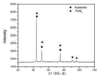
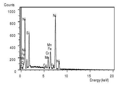
The XRD analysis results of high nickel ductile iron are shown in the figure.Five diffraction peaks, one strong diffraction peak, two sub-strong diffraction peaks and two weak diffraction peaks appear in the scanning process of 20theta from 20 to 100 degrees.The PDF comparison shows that the structure of the material is mainly composed of austenite matrix, i.e. white matrix with more distribution in the previous figure.According to literature reports, the austenite phase is increased due to the addition of a large number of Ni elements, resulting in a large area of austenite matrix as shown in the above figure; at the same time, intermetallic compound FeN I3 is also found in the structure of the diffraction results.FeN i3.FeN i3.However, it is generally accepted that FeN I3 meridian.However, it is generally accepted that FeN I3 meridian.However, it is generally believed that FeN I3 is highly inhomogeneous.To further understand the structure and composition of high nickel ductile iron, further analysis and testing were carried out by scanning electron microscope (SEM) and energy spectrum (EDS).
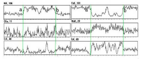
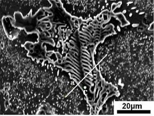
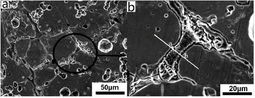
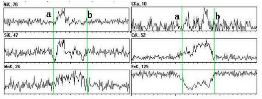
As can be seen from Fig. b, there are irregular substances at the grain boundary. The area is observed and analyzed by SEM and EDS. The test results are shown in the figure.According to the picture, the abnormal substances in the picture can be basically divided into two parts, one part is the white skeleton compound at the grain boundary, the other part is the black cut white skeleton material.Line scan is used to detect and analyze points a to B in the figure. The test results are shown in the figure.During on-line scanning, the peak values of Ni, C, Mn and Si are strong and basically continuous, while the peak values of Fe and Cr are relatively weak, which indicates that the substances in this area are composed of Ni, C, Mn, Si, Fe, Cr and other elements, and the content of Ni, C, Mn, Si is more, while the content of Fe and Cr is relatively small.During the line scanning from point a to point b, the carbon peak basically shows a continuous and stable change, and other elements increase or decrease.At point a, the peaks of C, Mn and Cr are weaker, and the peaks of Si are almost zero. However, the peaks of Ni and Fe are obvious here, which indicates that the area where the special-shaped material is located is basically composed of Fe-rich, Ni-rich materials and Mn or Cr-rich carbides.
To distinguish the composition of this special-shaped substance, the black area cut apart from the white skeleton-like substance is scanned, as shown in point C in Figure 3.7b. The scanned result shows that the atomic percentage content of Ni element in point C is 71.72%, the content of Fe is 15.36%, and the content of Si is 9.27%.The atomic ratio of Ni to Fe exceeds 3:1, which indicates that the black material at point C is FeN I3 gold FeN I3 gold FeN I3 intermetallic compound, and there is also Ni segregation at this point.The white skeleton-like material is Mn or Cr-rich carbide.
In order to distinguish easily, small carbides are found at grain boundaries for test analysis. The black ring area in the selection diagram a of the test section is shown in Figure B.And select the AB interval in Figure B for line scanning, the test results are shown in the figure.The result shows that the material is composed of elements such as Mn, Cr, C, etc. It is preliminarily judged that the white highlighted part is a mixture of carbides of Cr and Mn, and that FeN I3 gold is a mixture of carbides of Cr and Mn, and that FeN I3 gold is a mixture of carbides of Cr and Mn, and that FeN I3 intermetallics are in close contact with carbides, which makes it difficult to distinguish the boundary between them. At the same time, a small amount of Si is dissolved into Fe.
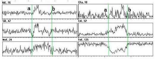
Select another irregular-shaped compound at the grain boundary as shown in the figure and perform a line scan of the AB interval in the figure as shown.The results show that the material composition here is still composed of elements such as Cr, Mn and C.
Based on the reports and combined with the above analysis, it is shown that the current ductile iron consists of austenitic matrix, Cr-rich carbide and intermetallic compound FeN i3, intermetallic compound FeN I3 and intermetallic compound FeN i3. Cror Mn-rich carbide (M2) and Cror Mn-rich carbide (M23C23C6C6) C6) are always distributed at grain boundaries.In addition, some other alloy elements are easy to segregate here, especially some other alloy elements such as Ni, Si, Mg, Mn, etc. are also easy to segregate here.According to Tammann’s law, the addition of alloying elements has a critical value, so the presence of Ni can be measured at the grain boundary.
Nodularity decline often occurs in high nickel ductile iron during casting as shown in the table.According to the traditional filling theory, the content of C, Si and Ni in high nickel austenitic ductile iron must satisfy a certain saturation degree (A) (Formula 3-2). When the content of C, Si and Ni is higher than a certain limit value (Saturation A), the graphite morphology will be fragmented.The data show that the saturation calculated by the formula can not exceed 4.4.
A>TC%+0.2Si%+0.06N%
The saturation of the high nickel ductile iron studied is 5.008, greater than 4.4, while the saturation of the high silicon molybdenum ductile iron is 4.04, less than 4.4. Therefore, the spheroidizing decay will occur in the high nickel ductile iron studied. The spheroidizing effect of the high silicon molybdenum ductile iron studied is better.