1. Introduction
In the field of casting, the production of high-quality cylinder heads is crucial for the performance and reliability of internal combustion engines. The WP10 cylinder head is an important component in certain engine models. However, due to 不合理的 casting process design, the casting scrap rate of the WP10 cylinder head was relatively high in the initial production stage. This not only led to increased production costs but also affected the overall production efficiency and product quality. Therefore, it is of great significance to analyze the casting defects of the WP10 cylinder head and improve the casting process.
The WP10 cylinder head has specific characteristics in terms of its sand box size, weight per piece, and casting conditions. The sand box size is 1200 mm×900 mm×300/300 mm, with 8 pieces cast per box, and each cylinder head weighs 20 kg, resulting in a total pouring weight of 220 kg per box. The initial pouring temperature is in the range of 1400 – 1420 °C. The cylinder head has a general wall thickness of 5 mm, with the thickest part being the bolt hole wall with a thickness of 30 mm. The sand cores near the inner gate are prone to sintering defects. The upper and lower molds of the WP10 cylinder head are made of green sand molding, while the upper and lower sandwich cores, intake and exhaust port cores, tappet cores, and fuel injector cores are all made of coated sand core making. The large skin core is made by cold core core making, assembled first and then dip-coated. Due to the large number and complex shape of the cores, the casting is prone to porosity defects.
In the small-batch production stage, the main defects of the WP10 cylinder head castings were porosity, sand holes, and local sintering and sand sticking defects. The comprehensive scrap rate of the castings was above 6.2%, and the scrap rate due to blowhole defects after casting processing was about 2%. This article mainly focuses on analyzing the causes of these three main defects and proposes corresponding improvement measures from the perspective of the casting process.
2. Porosity Defect Analysis and Process Improvement
2.1 Porosity Defect Status and Cause Analysis
The WP10 cylinder head has a complex structure with a large number of sand cores made of coated sand, which results in a large amount of gas generation during the casting process and 容易产生气孔缺陷. The pouring time per box is 24 – 26 s, and after pouring, many exhaust pins of the casting are not filled, as shown in Figure 1. After processing the upper plane, a relatively large proportion of porosity defects appear in the middle bridge area of the WP10 cylinder head, as shown in Figure 2.
The formation of porosity defects is mainly related to the gas pressure in the casting process. When the metal liquid enters the mold, the mold, sand core, coating, and binder gasify, decompose, or burn under the action of the heat of the metal liquid, generating a large amount of gas. As the temperature increases, the volume of the gas expands, resulting in an increase in gas pressure. When the gas pressure at a certain point on the interface is greater than the sum of the static pressure, resistance pressure, and surface tension pressure of the metal liquid at that point, the gas can enter the metal liquid to form porosity defects.
2.2 Solution Measures
2.2.1 Pouring System Process Improvement
In modern production conditions, reactive porosity and precipitation porosity are relatively rare, and invasive porosity is more common. To reduce porosity defects, we analyzed the cross-sectional area of the pouring system. The original cross-sectional area ratio of the pouring system was F_straight:F_cross:F_inner = 1:1.18:1.63, and the pouring time per box was 24 – 26 s. By increasing the cross-sectional areas of the straight runner and the cross runner, the improved cross-sectional area ratio of the pouring system was adjusted to F_straight:F_cross:F_inner = 1.04:1:1.3. As a result, the pouring time per box was shortened to 19 – 22 s, and the phenomenon of unfilled exhaust pins in the cylinder head was eliminated.
| Pouring System Parameter | Original Value | Improved Value |
|---|---|---|
| F_straight:F_cross:F_inner | 1:1.18:1.63 | 1.04:1:1.3 |
| Pouring Time per Box (s) | 24 – 26 | 19 – 22 |
2.2.2 Exhaust Process Improvement
For the 集中出现的 porosity defects in the middle bridge area of the WP10 cylinder head after processing, we analyzed that it was caused by the slower solidification of the iron liquid in the middle of the cylinder head. By adding an exhaust pin with a diameter of 10 mm and a height of 100 mm in the area where porosity is prone to occur during processing, as shown in Figure 3, the cooling speed of the area can be increased, and the porosity defects can be reduced.
In addition, the original design of the casting exhaust core head structure had problems with the sealing of the asbestos pad. By changing the sealing method of the asbestos pad to the upper sand mold compression method for plane sealing, the problem of poor sealing caused by extrusion deformation and deviation of the asbestos pad was reduced, thereby reducing porosity defects.
3. Sand Hole Defect Analysis and Improvement
3.1 Sand Hole Defect Status and Cause Analysis
The sand holes in the WP10 cylinder head mainly include two types. One type is located under the exhaust pins, with regular and fixed positions, as shown in Figure 4. The other type is scattered sand holes distributed on the bottom, top, and side surfaces of the casting without a fixed pattern, as shown in Figure 5.
The sand holes under the exhaust pins are mainly caused by the low height of the exhaust pins on the upper mold plate. When the drilling machine drills the air holes, the stroke is too large, causing the drilling machine to penetrate deeper, and the sand remains at the joint of the exhaust pins and is not easily blown off during the blowing process. The scattered sand holes are mainly due to the adhesion of some scattered sand on the upper sand mold during the host modeling process. After pouring, these scattered sands form sand holes. In addition, the bottom surface of the casting may also have small sand hole defects due to the structure of the chassis core.
3.2 Solution Measures
3.2.1 Increase the Height of the Exhaust Pins
To solve the problem of sand holes under the exhaust pins, we increased the height of all exhaust pins on the upper mold plate from the original 250 mm to 295 mm, and at the same time reduced the drilling stroke by 30 mm. This made the sand accumulation at the joint move up by 30 mm, which was beneficial for the upper box sand blowing personnel to blow off the sand and reduce sand hole defects.
3.2.2 Add an Automatic Sand Blowing Device
To deal with the scattered sand holes caused by the adhesion of scattered sand on the upper sand mold, an automatic sand blowing device for the upper mold was added before the box closing process to automatically blow off the scattered sand on the upper mold and reduce sand hole defects, as shown in Figure 8.
3.2.3 Optimize the Bottom Machining Allowance
To reduce the small sand hole defects on the bottom surface of the casting, the bottom machining allowance was optimized. By modifying the structure of the chassis core, the machining allowance within the range of the combustion chamber was gradually increased by 0.5 mm to remove the defect area during processing.
4. Sintering Defect Analysis and Process Improvement
4.1 Sintering Defect Status and Cause Analysis
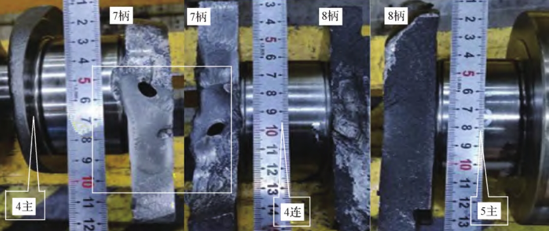
The sintering defect of the WP10 cylinder head mainly occurs near the inner gate, where the sand core is surrounded by the main bolt hole area, and the casting wall thickness is 30 mm. After pouring, this area is heated for a long time, resulting in the sintering of the sand core, as shown in Figure 9.
4.2 Solution Measures
To solve the sintering defect, we first analyzed the size of the 易产生烧结的部位. The theoretical size of the thick part of the bolt hole is 35 mm, and the unilateral wall thickness after processing is 6.3 mm. After dissecting and measuring the processed casting, the size was found to be consistent, and the wall thickness at this position was at the upper limit according to the product design requirements (5 mm ± 1.0 mm). Therefore, we decided to optimize the structure of this area by increasing the thickness of the sand core in the 易烧结部位 by 1.0 mm to improve the heat resistance of the sand core and reduce sintering defects. At the same time, we used zircon powder coating with better heat resistance to pre-coat this area. Utilizing the high fire resistance of the zircon powder coating, the fire resistance of the sand core in this area was improved, and the sintering caused by the overheating of the inner gate was reduced.
5. Improvement Effect
After the implementation of the above process improvements and strict operation, the comprehensive scrap rate of the WP10 cylinder head castings gradually decreased. From December 2013 to February 2014, it has continuously remained below 1.5% for three months, achieving good results, as shown in Figure 10.
6. Conclusion
In this article, we analyzed the casting defects of the WP10 cylinder head and proposed corresponding improvement measures. The following conclusions can be drawn:
- A reasonable ratio of the cross-sectional areas of each element of the pouring system can control the pouring speed per box, and a reasonable pouring speed can effectively reduce porosity defects.
- Adding exhaust pins in the slower cooling areas of the casting is an effective measure to solve the problem of local 集中出现的 porosity.
- Ensuring the good sealing of the casting exhaust holes can effectively reduce porosity defects.
- The reasonable combination of process parameters and equipment parameters can reduce sand hole defects.
- Optimizing the local thickness of the sand core and using high fire resistance coatings can reduce casting sintering defects.