According to the above casting process analysis and site production conditions of the foundry, the casting process route is determined to be: static pressure line clay sand molding, using hot core box to make sand core, medium frequency furnace melting molten iron casting, external shot blasting and internal cavity shot blasting, size scanning, UT flaw detection and sampling and planing detection of trial production samples. The initial casting process plan uses simulation software to simulate the pre-casting process, predict and verify the filling and solidification process, and optimize it in the early virtual state.
1. Analysis of pouring position
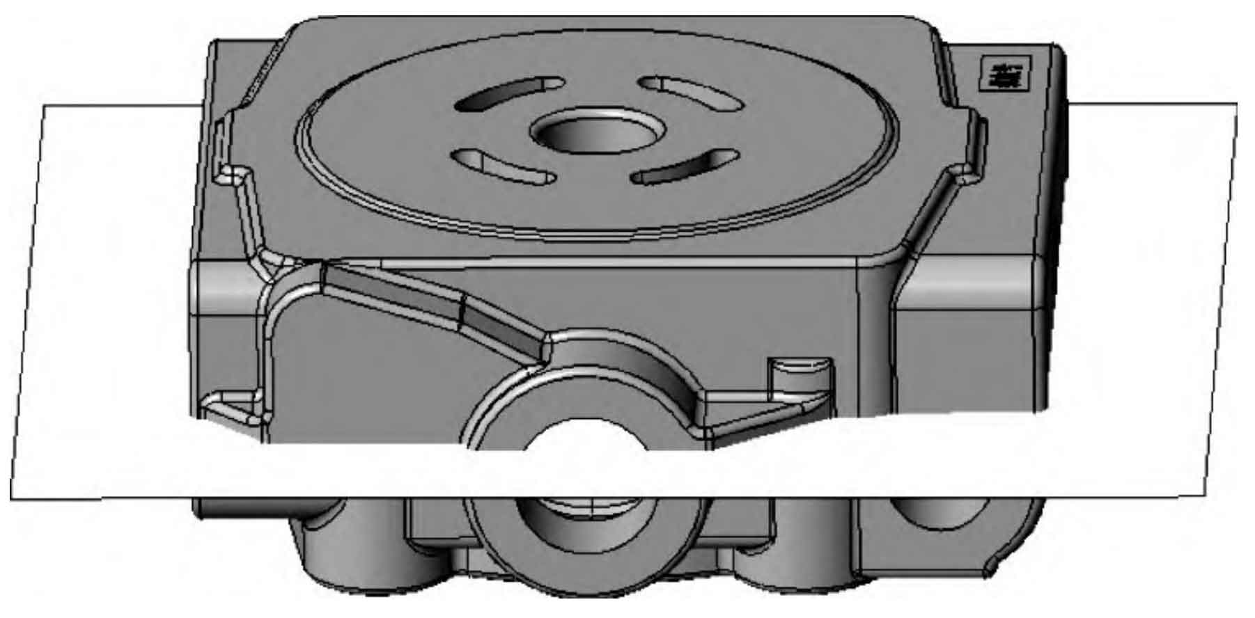
In consideration of the stability of the lower core of the sand core and the moldability of the ductile iron castings, it is determined that the pump cover ductile iron castings are set at the maximum surface, and the upper and lower sand boxes are half of the ductile iron castings cavities. The side riser is set on the parting surface, and the inner gate passes through the side riser, which increases the overheating of the side riser during the solidification process and is conducive to feeding. As shown in Figure 1, the position of parting surface.
2. Size control of ductile iron castings
The structure of the pump cover nodular cast iron is relatively complex. According to the shrinkage law of the nodular cast iron body, it is specified that the casting shrinkage of the mold production should be controlled by 0.8%, and the main machining allowance should be controlled by 3 mm, so as to form the oil channel sand core inside the nodular cast iron part, which is assembled by 6 independent sand cores. Large mold manufacturing error will cause errors in the matching between the external oil port of the pump cover and the valve plate and other components. In order to ensure the accuracy of the mold, the mold processing is required to be CNC integrated processing. After the mold manufacturing is completed, it must be trial-produced after passing the three-dimensional scanning inspection.
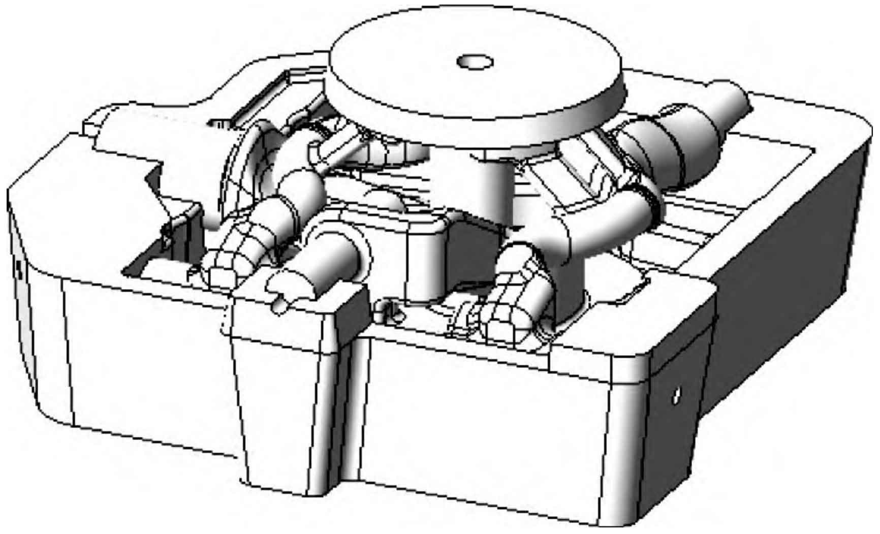
3. Sand core design
The pump cover oil channel comprehensively evaluates the moldability of the core making mold and follows the premise that the sand cores are assembled as a whole as little as possible. The core head positioning is designed between the sand cores. In order to ensure the accuracy of the oil hole size, the core clearance is controlled by 0.15 mm. A vent hole is added in the center of the straight section of the sand core to ensure the smooth discharge of the gas generated by the burning of the sand core coated sand during pouring, and to prevent bubbles from entering the molten iron to form pore defects. Fig. 2 Schematic diagram of sand core after assembly.