
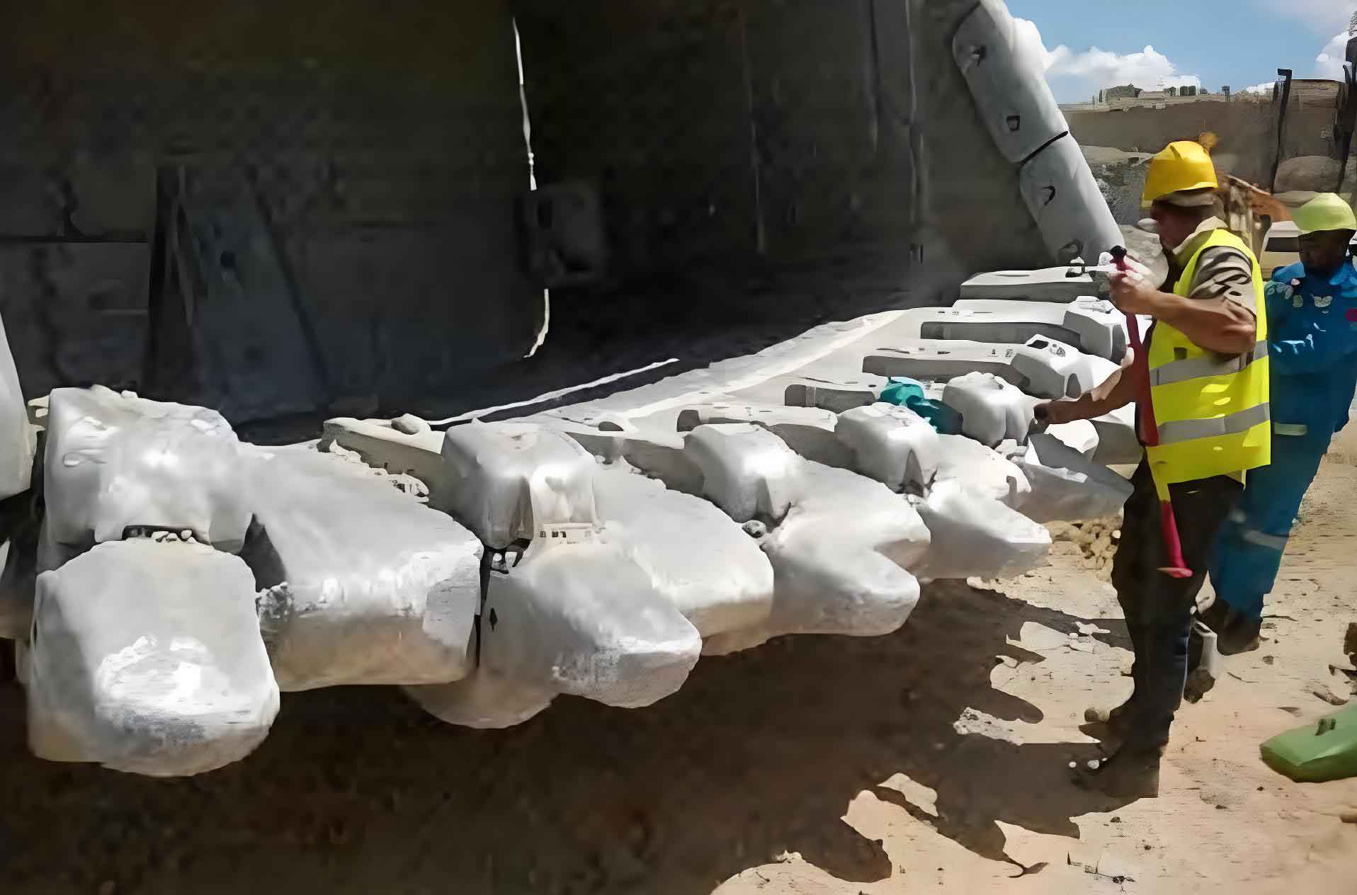
Excavators are extensively used in construction, roadwork, and underground engineering due to their high power and efficiency. The hydraulic control valve system serves as the heart of these machines, with the multi-valve body being a critical excavator casting part. This component demands exceptional pressure resistance and dimensional precision. Our company developed a QT500-7 ductile iron valve body weighing 89 kg with dimensions 360 mm × 265 mm × 65 mm using optimized casting techniques.
We implemented a green sand molding process with shell cores made from coated sand. Pattern layout featured one cast per mold, with key technical considerations detailed below.
1. Linear Contraction Control
Precise contraction management was vital for this excavator casting part due to tight machining allowances (0.5 mm at valve bore ends). Differential contraction rates were applied:
- Valve bore axis (120 mm range): 0.3% contraction
- Other regions: 0.6% contraction
The formula for contraction compensation is expressed as:
$$ D_{mold} = D_{final} \times (1 + C) $$
where $D_{mold}$ is mold dimension, $D_{final}$ is finished part dimension, and $C$ is contraction rate.
2. Gating and Feeding System
An open gating system with ratio $F_{gate}:F_{runner}:F_{sprue} = 1.4:1.2:1$ ensured smooth filling. Two top risers (Ø130 mm × 180 mm) with chills were positioned at critical sections to eliminate shrinkage in pressure-bearing zones:
| Riser Parameter | Value |
|---|---|
| Diameter | 130 mm |
| Height | 180 mm |
| Location | High-stress junctions |
Solidification modeling confirmed this configuration achieved directional solidification toward risers.
3. Core Production and Assembly
The complex internal geometry required over 30 sand cores from 20 designs. We selected NFS CER90 coated sand (50–90% artificial sand) for its flowability, strength, and collapsibility. Core assembly challenges included:
- Deep flat cavity filling difficulties
- Limited space for joint repairs
- Gas venting constraints
HA-type coating was applied to cores to prevent burn-on and improve surface finish.
4. Molding and Venting
Using a KW molding line with flask dimensions 800 mm × 600 mm × 300/300 mm, we addressed gas evolution from resin binders through:
- Vent holes drilled through overflow risers
- Permeability >100 in mold sand
- Strategic vent placements near core assemblies
Vent capacity was calculated using:
$$ Q_v = 0.03 \times W \times \frac{T_p}{273} $$
where $Q_v$ is vent capacity (m³), $W$ is metal weight (kg), and $T_p$ is pouring temperature (K).
5. Melting and Treatment
Composition control was critical for this high-integrity excavator casting part:
| Element | Composition Range (%) |
|---|---|
| C | 3.85–3.95 |
| Si | 2.45–2.65 |
| Mn | 0.35–0.45 |
| Sn | 0.020–0.030 |
| S | ≤0.02 |
| P | ≤0.05 |
Key melting parameters:
- Charge materials: Q10 pig iron, steel scrap, 65% FeMn
- 3-ton medium-frequency furnace
- Treatment: T-1 nodularizer (1.3%), three-stage inoculation
Inoculation distribution:
| Stage | Inoculant | Addition (%) |
|---|---|---|
| Bottom | Ca-Ba inoculant | 0.25 |
| Mid-pour | 75% FeSi | 0.35 |
| Top | 75% FeSi | 0.30 |
Pouring temperature was maintained at 1,480–1,500°C.
6. Pouring Parameters
Critical pouring metrics for the excavator casting part:
- Target temperature: 1,390–1,320°C
- Total metal weight: 142 kg
- Pouring time: 17–21 s
Pouring time was calculated using:
$$ t = 1.47 \sqrt{W} $$
where $t$ is time (seconds) and $W$ is metal weight (kg). Stream inoculation (0.1% FeSi) occurred during pouring for fade resistance.
7. Trial Results and Defect Analysis
Three trial casts were produced with monitored parameters:
| Parameter | Value |
|---|---|
| Tap temperature | 1,492°C |
| Pour temperature | 1,362–1,386°C |
| Pour time | 18–21 s |
Mechanical properties exceeded QT500-7 requirements:
| Property | Value |
|---|---|
| Tensile strength | 560 MPa |
| Yield strength | 370 MPa |
| Elongation | 12% |
| Hardness | 179 HB |
Measured contraction matched predictions:
- Valve bore region: 0.35%
- Other sections: 0.68%
Internal integrity was confirmed through sectioning – no shrinkage defects were found in critical areas.
8. Defect Resolution
Initial trials revealed three critical defects in the excavator casting part:
8.1 Core Lift
Caused by thin-core fracture at sharp transitions (2 mm radii) and metal impingement. Solutions:
- Increased core draft angles
- Changed from top to step gating
Gating modification reduced metal velocity $v$ according to:
$$ v = \frac{Q}{A} $$
where $Q$ is flow rate and $A$ is cross-sectional area.
8.2 Distortion
Up to 2 mm bore misalignment resulted from core head gaps and mold yielding. Corrective actions:
- Added core reinforcements
- Modified core head support to shell contact
8.3 Surface Pitting
2–3 mm deep pits formed from sand sintering and gas entrapment. Improvements:
- Upgraded to HA high-temperature coating
- Uniform high-grade sand for all cores
- Added core vents
9. Validation and Production
After process optimization:
- Core lift eliminated
- Distortion reduced to 0.6 mm
- Pitting significantly diminished
Thirty excavator casting parts were subsequently produced with consistent quality. Machining trials and pressure testing confirmed dimensional accuracy and leak-tightness up to 350 bar. The process is now approved for batch production, with ongoing refinement for pitting elimination.
This development demonstrates that complex hydraulic components like excavator casting parts can be reliably manufactured through controlled contraction management, systematic gating design, and rigorous process discipline.