
The front bearing seat is an important component of the front suspension system of a car, usually installed above the chassis of the vehicle to support and fix the bearings that rotate the front wheels. In addition, in the aviation industry, the landing gear of an aircraft also requires the use of front bearing seats to support and secure the wheels of the aircraft. The function of the front axle seat is to maintain a stable connection between the wheels and suspension system, providing wheel support and bearing support for movement, thereby making vehicle driving smoother and more comfortable. The front bearing seat usually has sufficient strength and rigidity to withstand various forces and loads during vehicle operation.
Gray cast iron is a commonly used casting alloy material with the characteristics of easy casting and good mechanical properties. It is suitable for bearing small and medium-sized loads and impacts, and has advantages such as good seismic performance, good machinability, and low cost. It is suitable for parts and mold manufacturing, automotive parts and mechanical structures, and other fields. The front bearing seat mainly serves as a connection, and the stress situation is complex. In order to ensure that the part has good comprehensive performance, defects such as shrinkage, porosity, porosity, and sand inclusion should be avoided during gray cast iron casting.
ZHY Casting will use HT-250 gray cast iron as the casting material. By analyzing the structural characteristics of gray cast iron castings, the pouring system, riser, cold iron and other parts of the front half gray cast iron castings of the bearing seat will be designed. Using the gray cast iron casting simulation software ProCAST to simulate and analyze the metal liquid filling, solidification heat transfer, and shrinkage porosity defects during the pouring process. Taking into account the structural characteristics of gray cast iron castings and optimizing the gating system multiple times. By analyzing simulation results and continuously optimizing the size and position of the riser and cold iron, the ultimate goal is to prevent and eliminate casting defects such as shrinkage and porosity in gray cast iron.
1. Process analysis of parts
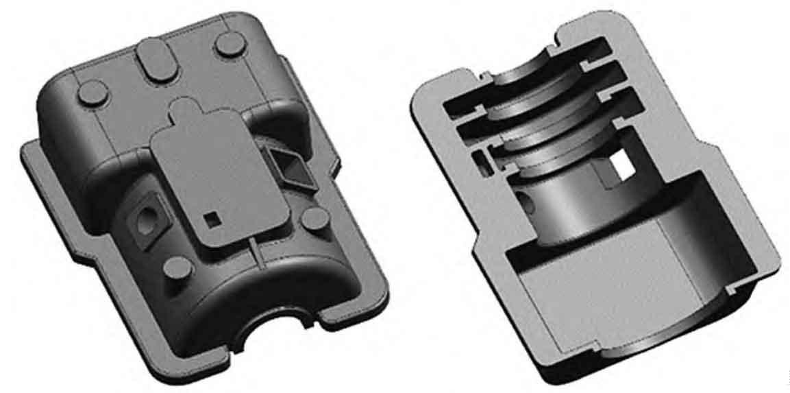
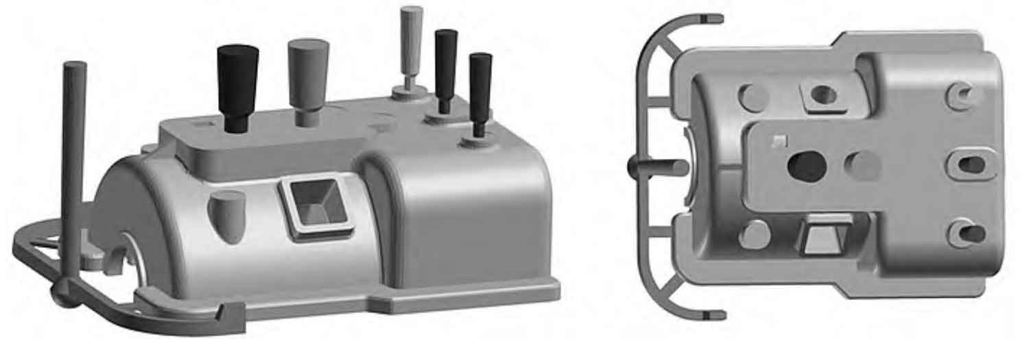
The three-dimensional structural solid diagram of the upper half of the front bearing seat supporting the bearing and fixing the outer ring of the bearing is shown in Figure 1. The external dimensions are 1085 mm x 810 mm x 380 mm, with a maximum wall thickness of 150 mm and a minimum wall thickness of 20 mm. The net weight is 566 kg. The cavity structure is complex, and it is difficult to fill with metal liquid. In addition, there is a significant wall thickness difference at some structural turning points, which can easily generate hot spots. The oil injection hole is a slender curved cavity, which makes the sand core easily damaged during metal liquid filling. The overall structure of the parts is relatively symmetrical, and the upper and lower large planes are important machining surfaces. Technical requirements: Gray cast iron castings are not allowed to have defects such as shrinkage, porosity, porosity, and sand inclusion that affect their performance.
The upper half of the front bearing seat belongs to medium-sized gray cast iron castings, which are produced in small batches and are manually molded. To ensure high dimensional accuracy and surface quality of gray cast iron castings, furan urea formaldehyde resin sand with high bonding strength, good heat resistance, and low gas generation is selected as the molding material. According to the requirements of gray cast iron casting technology, the parameter selection of gray cast iron casting process is as follows: size tolerance grade is CT13, machining allowance is G, shrinkage rate of gray cast iron casting is 0.9%, cutting allowance of sprue and riser is selected as 3mm. Based on the quality and wall thickness of gray cast iron casting and the process manual, it is found that the cooling time of gray cast iron casting is 1 hour.
2. Design and analysis of gray cast iron casting process
2.1 Selection of pouring position and parting surface
Based on the characteristics of gray cast iron castings, we have determined two pouring positions and parting surfaces, as shown in Figure 2.
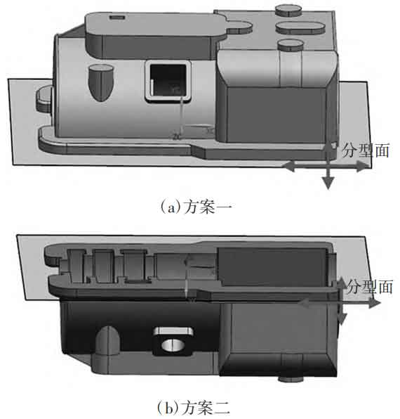
By analyzing and comparing the above two schemes, we can understand their different characteristics:
Option one can effectively ensure the accuracy of the bearing groove, facilitate molding, ensure smooth filling, and avoid uneven pouring. The disadvantage is that the bearing base is on top, which leads to low surface accuracy, so it is necessary to increase the machining allowance before processing. And there are many thick walls at the bottom, which can easily form hot spots. Option 2: Place the bottom surface of the bearing seat at the bottom to ensure accuracy and prevent defects such as sand holes, air holes, and slag inclusions. The disadvantage is that the sand box needs to be flipped over during molding, which can easily cause damage to the sand mold.
Considering that the narrow top and wide bottom of the mold cavity during solidification in Plan One is not conducive to shrinkage, and it is easy to form hot knots and shrinkage pores, and the use of a large amount of external cold iron cannot effectively eliminate these defects, it is decided to choose Plan Two’s pouring method.
2.2 Pouring System Design
2.2.1 Selection of pouring system type
The pouring system not only serves as a channel for filling the molten metal, but also ensures smooth flow, unobstructed exhaust, easy slag blocking, and helps to regulate the temperature field of molten metal solidification, reducing solidification defects in gray cast iron castings. Based on the principles of pouring system design, the preliminary design scheme is shown in Figure 3.
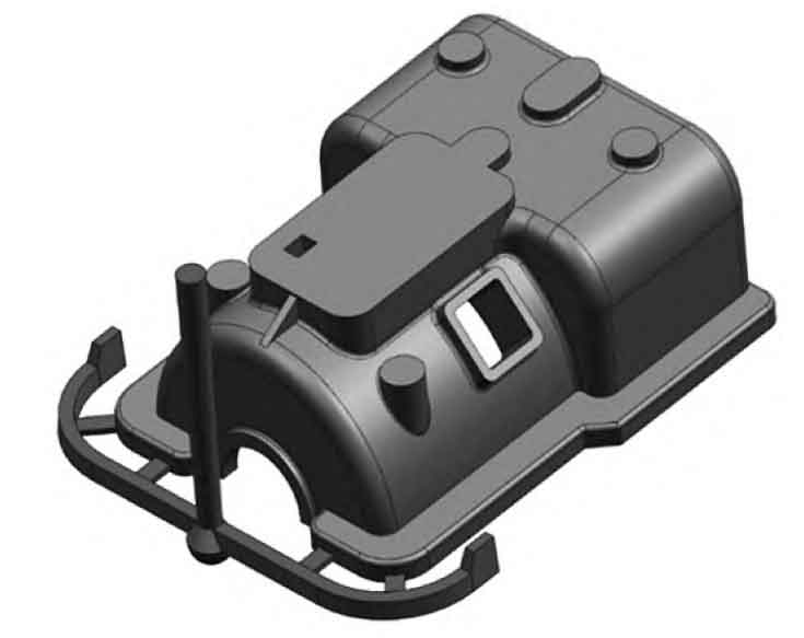
The bottom pouring system is adopted, which is characterized by the inner runner working basically in a fully filled state, smooth filling, and can avoid splashing and oxidation of the metal liquid, which can form defects in gray cast iron castings. The pouring system type adopts a semi enclosed pouring system, which has a certain slag blocking ability and can ensure moderate metal liquid flow rate, suitable for various types of gray cast iron parts. For medium-sized gray iron parts, according to the Casting Process Design Manual [8], the cross-sectional area ratio of each runner is selected as Σ A straight: Σ A horizontal: Σ Within A:=1:1.25:0.83.
2.2.2 Calculation of flow resistance cross-section
According to the Casting Process Design Manual, for medium and large gray cast iron castings with a pouring weight of less than 1000 kg, the calculation can be carried out according to equation (1):
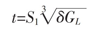
In the formula: t is the pouring time, in seconds; δ The average wall thickness of gray cast iron castings, in millimeters (for structurally complex gray cast iron castings,…), δ Take the wall thickness of the main part); S1 is the coefficient. In general, S1 is taken as 2. When there is an external or internal cold iron and fast pouring is required, S1 is taken as 1.7~1.9 [8]; GL is the weight of molten iron, in kilograms.
The final calculation shows that the pouring time is 43 seconds. The sprue should have a minimum height to create sufficient pressure, making the contour of the gray cast iron casting clear and avoiding failure to pour. The height of the sprue is usually equal to the height of the upper mold, and the pressure angle can be used to check whether the height of the upper mold is sufficient. Refer to the “Casting Process Design Manual” [8] for the calculation of the minimum remaining head (upper mold height) HM:
In the formula, L represents the process of molten metal, that is, the horizontal distance from the highest and farthest point of the gray cast iron casting to the centerline of the sprue, in millimeters; α Is the pressure angle, in degrees; HM is the minimum remaining head (upper height), measured in millimeters.
The final calculation shows that the height from the sand box to the top surface of the gray cast iron casting should be greater than 170 mm, and the static pressure head Hp should be 360 mm. Using the obstruction section design method, calculate the minimum cross-sectional area of the runner according to the Ozan formula:
In the formula, Ag is the minimum cross-sectional area of the pouring system, in cm ^ 2; G is the total mass of the metal liquid flowing through the blocking section, in kilograms, taken as 700; ρ Is the density of the metal liquid, in g/cm ^ 3, taken as 7.2; T is the total filling time, in seconds, taken as 43; μ When filling all the cavities, the flow coefficient of the blocking section of the pouring system is taken as 0.5; Hp is the average calculated pressure head when filling all cavities, in cm, taken as 36; G is the gravitational acceleration (981 cm/s2).
By inputting the parameters into the formula, Ag can be obtained as 17 cm ^ 2.
2.2.3 Design of dimensions for each sprue
According to the Casting Process Design Manual, the cross-sectional ratios of each runner are Σ A straight: Σ A horizontal: Σ A:=1.2:1.5:1, the area of the sprue can be obtained as 20.4 cm2, with a minor diameter of 50 mm and a major diameter of 62 mm, and a length of approximately 600 mm.
The total area of the runner is 25.5 cm ^ 2, with two trapezoidal runners, one with an area of 12.75 cm ^ 2.
The total area of the internal sprue is 17 cm ^ 2, with 4 trapezoidal internal sprues, one with an area of 4.25 cm ^ 2.
2.2.4 Gate Cup Design
Gate cups are divided into two categories: funnel-shaped and pool shaped. In this process, pool shaped gate cups are used, and the two-dimensional diagram of the gate cup is shown in Figure 4.
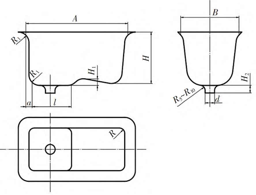
The capacity of the sprue cup is 125 kg, and the corresponding size is: A=450 (mm); B=250 (mm); I=130 (mm); H=185 (mm); H1=20 (mm); D=60 (mm); A=25 (mm); R=40 (mm); R1=25 (mm); H2=65 (mm).
3. Simulation and analysis of grey cast iron casting process plan
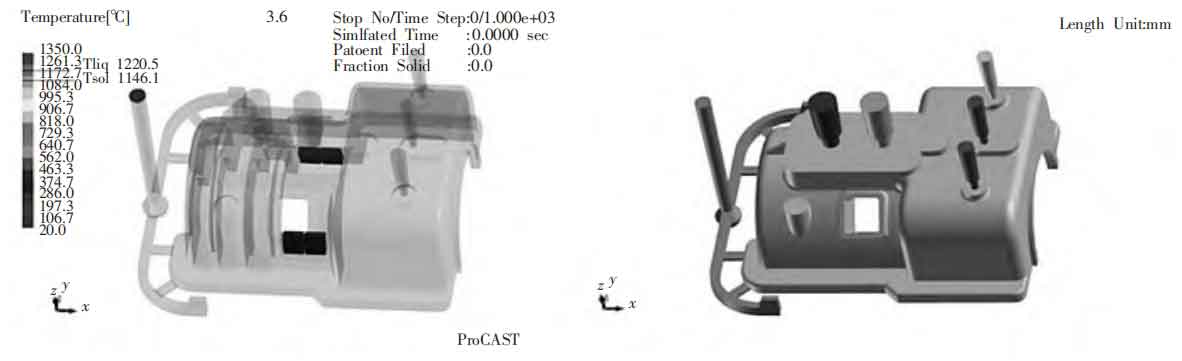
The ZHY Casting process used UG 3D modeling software for solid drawing, imported into ProCAST for surface and volume mesh division. After correction, the 2D elements of the gray cast iron casting model were 120164, and the 3D elements were 2272604. The pouring temperature is 1350 ℃ and the pouring time is 43 seconds.
3.1 Simulation Results and Analysis
3.1.1 Filling process
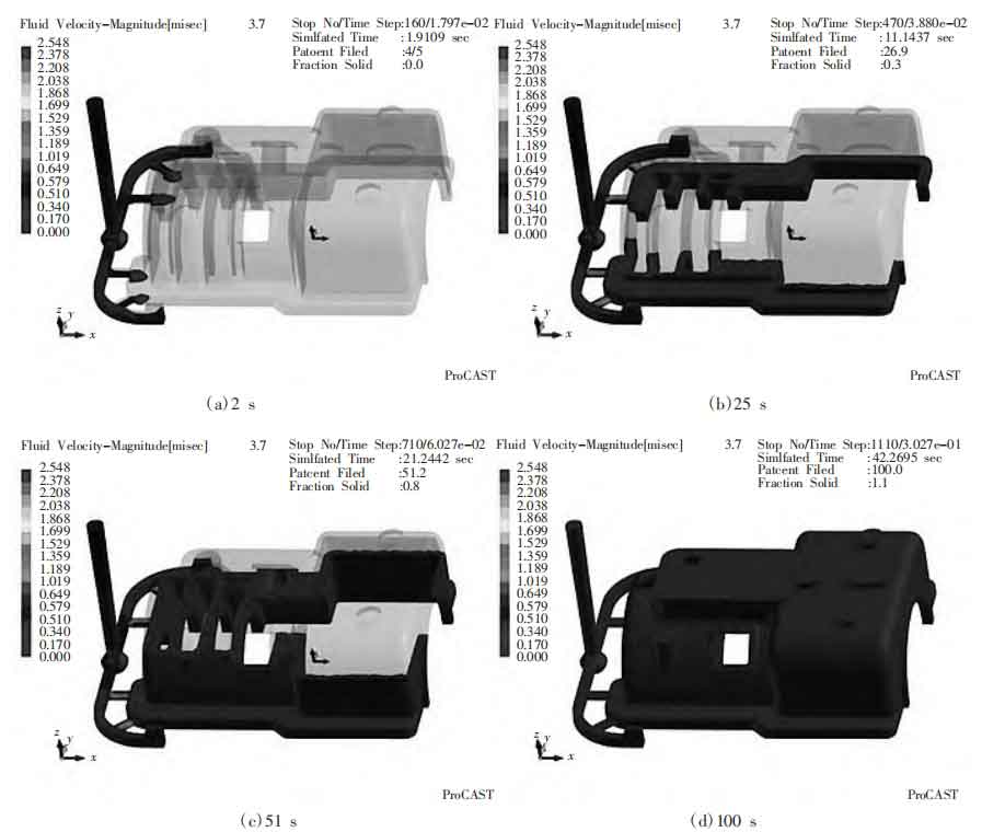
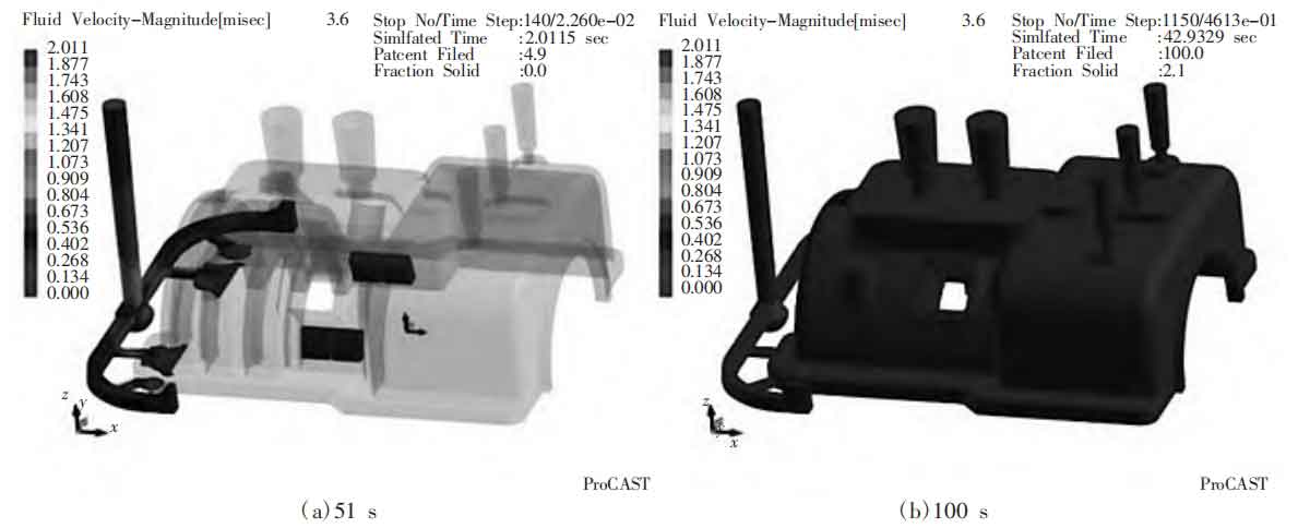
Simulate the filling process of the original gray cast iron casting, and the filling speed field is shown in Figure 5. From Figures 5a and 5b, it can be seen that the molten iron enters the gray cast iron casting at around 1.9 seconds, fills the bottom of the gray cast iron casting at around 10 seconds, and takes 43 seconds to fill the entire mold cavity. The pouring method for this design is double-sided bottom pouring, but at the beginning, the two sides of the gray cast iron casting were separated, and there was no convection on both sides after the metal liquid entered. The molten iron undergoes convection at the middle ring, as shown in Figure 5c, but the flow rate is relatively stable at this time, and the liquid level begins to rise steadily, so it will not have a significant impact. As shown in Figure 5d, all the gas is concentrated at the top of the gray cast iron casting, mainly composed of air in the mold cavity. In the later stage, a riser or exhaust needle can be added to solve this problem.
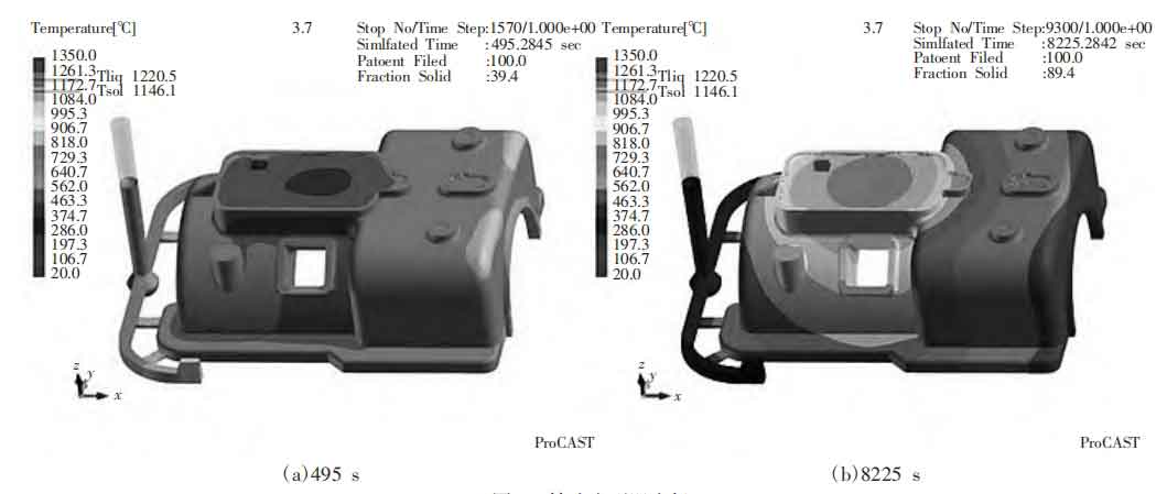
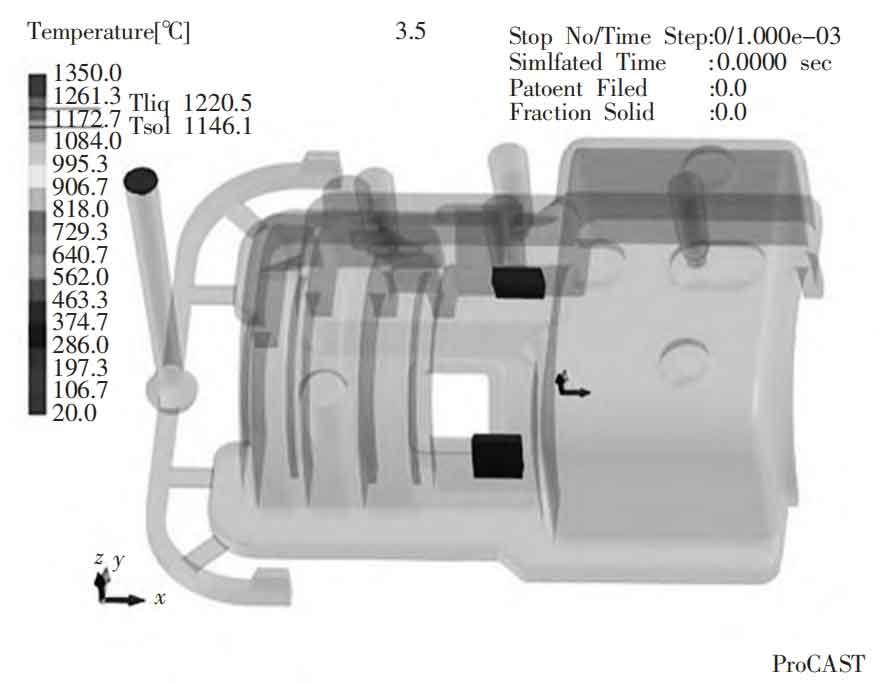
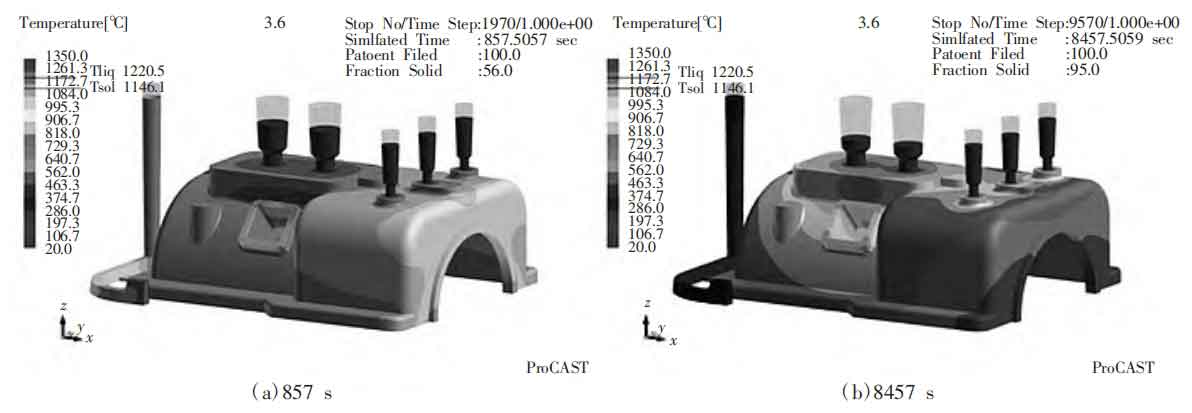
The temperature field changes of gray cast iron castings during the filling process are shown in Figure 6. Figure 6a shows that the temperature of the top thin-walled part of the gray cast iron casting is relatively low during the filling process. Due to the better cooling effect of the square hole and base, the central part finally cooled down, resulting in an overheated area between the square hole and the middle part of the gray cast iron casting base. From the temperature distribution in Figure 6b, it can be seen that the cooling trend of the entire gray cast iron casting is from right to left and from bottom to top. Final optimization can be carried out based on its solidification trend.
3.1.2 Analysis of defects during solidification process
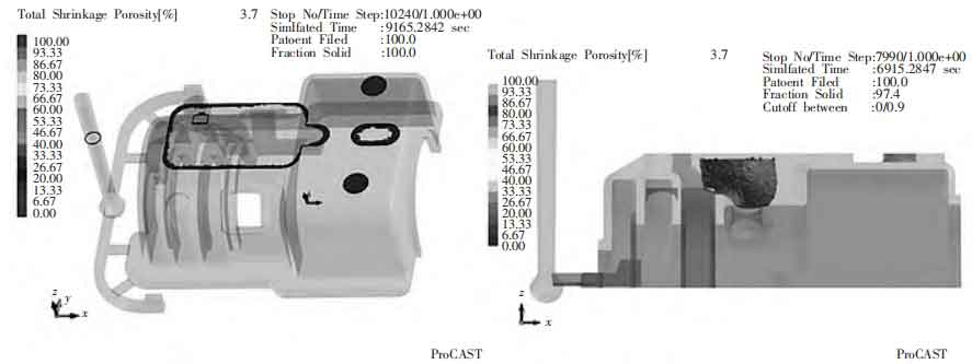
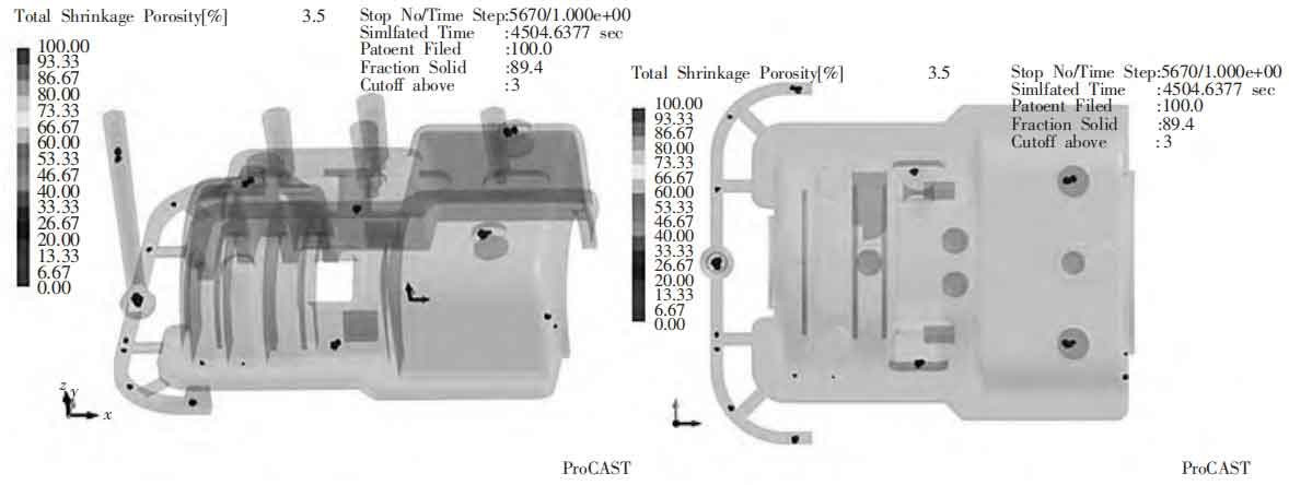
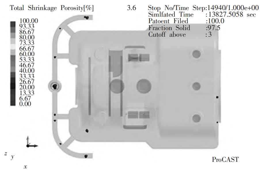
The defects in bottom pouring mainly exist in four places, as shown in Figure 7. The first is the three small protrusions on the right side of the top, the second is the thicker protrusion on the top, the third is the overheated area between the side holes and the base of the gray cast iron casting, and the fourth is the pouring system. The calculated shrinkage volume accounts for 0.48% of the total volume.

The top of the gray cast iron casting is relatively thick, and the molten iron has not been replenished in a timely manner, resulting in a depression phenomenon. It is also the final solidified part with a hot spot, as shown in Figure 8. The problem of shrinkage can be solved by adding a riser, while also solving the problem of gas discharge and top depression; Add cold iron on both sides of the bottom to accelerate cooling.
3.2 First optimization
3.2.1 Preliminary design and calculation of riser
The formula for calculating the size of the riser is as follows:
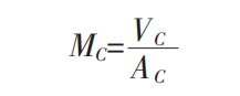
In the formula: MC is the modulus of the gray cast iron casting set at the riser, VC is the volume of the gray cast iron casting at the riser neck, and AC is the heat dissipation area at the riser neck.
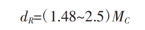
In the formula, dR is the diameter of the riser neck, and MC is the modulus of the gray cast iron casting with the riser set.
According to the design principle of the top exposed riser of gray iron parts in the Casting Process Manual, as shown in Figure 9a, DR=(1.55-2.0) dR is usually taken. Use HR=(2-4) DR as the size of the riser. As shown in Figure 9b, three risers are installed at the left protrusion, with each riser having a DR of approximately 60 mm and an HR of 182.16 mm. Set a riser at the right protrusion, with a riser DR of approximately 60 mm and an HR of 181 mm.
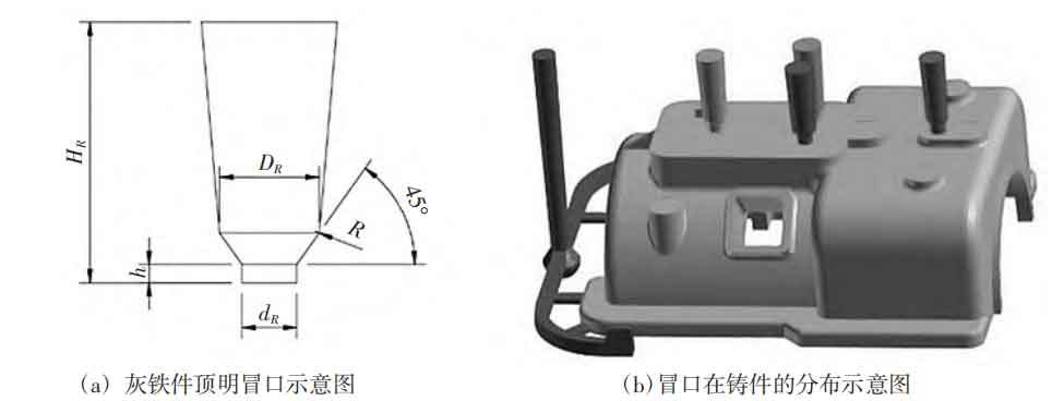
During solidification, the larger the volume of the object and the smaller the heat dissipation area, the greater the modulus and the longer the solidification time. Therefore, four risers with a diameter of 60 mm and a height of 181 mm were used, as shown in Figure 9.
3.2.2 Location design of cold iron
According to the analysis of preliminary simulation results, the position of the cold iron design is at the center of the square holes on both sides of the gray cast iron casting and the bearing base. Setting cold iron here can improve the solidification sequence of the gray cast iron casting, striving for a bottom-up solidification sequence of the gray cast iron casting. Under the action of gravity, the metal liquid above can be replenished to form a dense structure, ensuring the quality of the detection area of the gray cast iron casting; Secondly, a cold iron is installed in this area to subject the molten metal to quenching, reduce defect formation, refine the grain size, and optimize mechanical properties.
The size calculation of cold iron is as follows:
In the formula: δ T is the thickness of the external cold iron, and T is the diameter of the hot spot circle of the gray cast iron casting. By simulation, the diameter of the hot spot circle at the location where the cold iron is placed is 75 mm. The calculated thickness of the outer cold iron is 30 mm, and the length is selected as 100 mm. The placement position of the cold iron is shown in Figure 10.
3.3 First optimization results and analysis
By adding a riser for the first optimization of the pouring system, as shown in Figure 11, the number of defects has been significantly reduced. Especially the thickest part at the top, due to the feeding of the riser, both the shrinkage and concavity disappear. But there are still the following problems: there are still obvious defects on both sides (holes and center of base) of gray cast iron castings; The distribution of risers is unreasonable, and the solidification of the small protrusion on the right side of the top is slow, which has not been supplemented and resulted in shrinkage and looseness; As shown in Figure 12, there are slightly more top risers, which leads to slower solidification in this area, resulting in hot spots, and the size of the left riser is smaller.
3.4 Second optimization of gray cast iron casting process
Based on the existing problems mentioned above, firstly, the number of cold iron has been adjusted from two to four. Secondly, two small risers have been added to the other two small protrusions at the top, mainly to eliminate shrinkage and porosity. Finally, the three risers at the larger protrusions have been merged into two, and the size has been increased to a certain extent. The modified quantity of cold iron and the position of the riser are shown in Figure 13.
The size of the riser at the left protrusion is adjusted as follows: two risers are set at the thicker protrusion, with each riser having a DR of approximately 90 mm and an HR of 270 mm. The size of the riser at the right protrusion is adjusted as follows: three risers are set at the thicker protrusion, with each riser having a DR of approximately 41 mm and an HR of 123.5 mm.
3.5 Analysis of Secondary Optimization Results of Gray Cast Iron Casting Process
3.5.1 Analysis of Secondary Optimization Filling Process
After optimizing the quantity and size of the riser and cold iron, the filling speed field of the gray cast iron casting is shown in Figure 14a. The molten iron enters the gray cast iron casting around 2 seconds and fills the bottom of the gray cast iron casting around 10 seconds. It takes a total of 42 seconds for the metal liquid to enter the mold cavity and fill it. Figure 14b shows that during the casting process of gray cast iron, the gas is mainly concentrated above the molten metal, and the riser is located at the top of the gray cast iron casting, so the gas is finally discharged from the riser. The corresponding filling temperature field is shown in Figure 15.
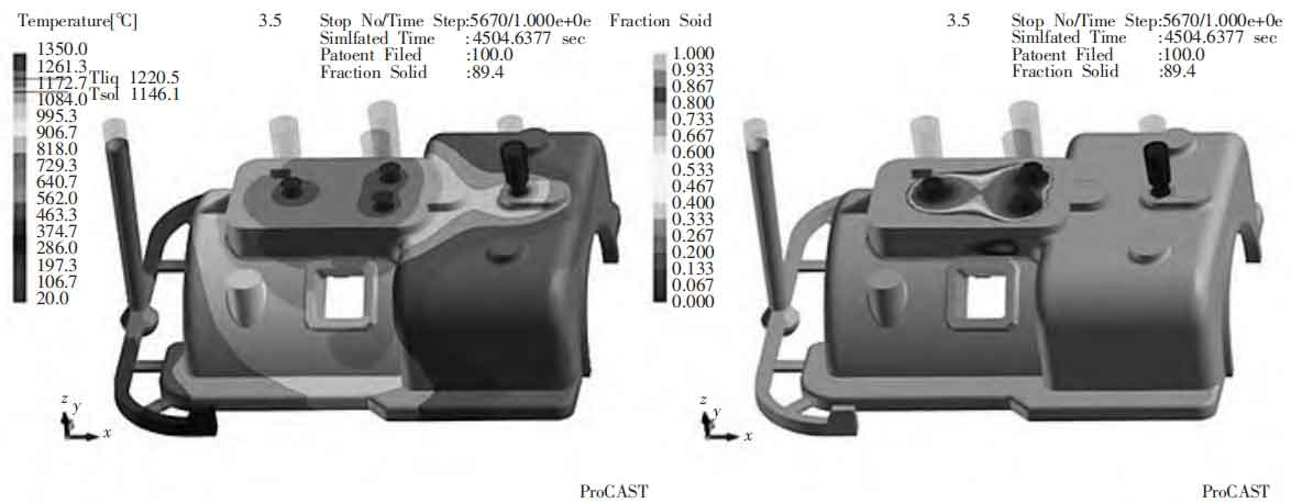
From Figure 15a, it can be seen that the temperature distribution of the entire gray cast iron casting is relatively uniform. The addition of cold iron between the square hole and the base ensures that the temperature during the filling process is consistent with the surrounding area, thus effectively eliminating the defects in this area. From Figure 15b, it can be seen that due to the addition of insulation risers, the final solidification area of gray cast iron castings is concentrated in the top convex part, and this area is filled with molten metal in the riser.
3.5.2 Analysis of defects in the secondary optimization pouring process
After filling, the solidification shrinkage diagram of gray cast iron castings is shown in Figure 16. From the figure, it can be seen that the defects in gray cast iron castings have been greatly improved, and all defects in key areas have been eliminated. Most of the defects are mainly concentrated in the pouring system, which has no impact on the quality of the entire gray cast iron casting. From Figure 17, it can be seen that because the added riser is an insulation riser, the metal liquid inside the riser has not solidified, and the hot spots are also concentrated in the riser. The gray cast iron casting part also no longer has hot spots, and the overall shrinkage effect is good. The optimized pouring system is shown in Figure 18.
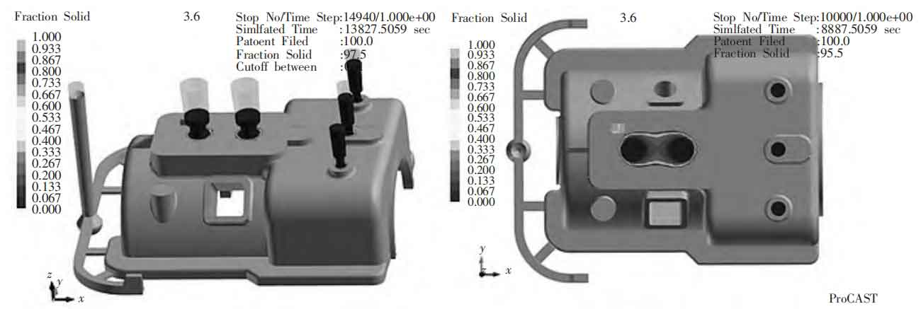
3.6 Final gray cast iron casting process plan
After simulation analysis, the optimal pouring method was ultimately determined to be bottom pouring. First, the bearing base was facing upwards for split molding, and after molding, the sand box was poured in reverse to avoid the working part of the gray cast iron casting being at the top of the casting and the overall inspection part being at the bottom of the gray cast iron casting. Under the action of gravity, it solidified first to obtain a dense structure, ensuring the quality inspection results and improving the working performance of the gray cast iron casting. The modeling method adopts manual modeling, with two box modeling; Choose alkaline phenolic resin self hardening sand as the molding material; The pouring system is a semi closed bottom pouring type, Σ A straight: Σ A horizontal: Σ Within A=1:1.25:0.83; Add two risers to the top left convex platform and three small risers to the right convex platform; Place two pieces of cold iron on each side of the overheated semi enclosed part of the gray cast iron casting; The production rate of the process is η= 90.5%.
4. Conclusion
The upper half of the front bearing seat of this gray cast iron casting underwent a series of process design and numerical simulation analysis, ultimately forming a gray cast iron casting with minimal defects and no shrinkage. The main processes include:
(1) The pouring method is bottom pouring, and the pouring system is a semi closed pouring system. This pouring method has a smooth filling and greatly reduces the occurrence of defects;
(2) Through the initial numerical simulation analysis, it was found that the main defects of gray cast iron castings are concentrated at the top. Observing the last destination of the molten metal and adding a riser at the corresponding position on the top, the riser here has three main purposes: to achieve the effect of filling and shrinking, and to avoid the effect of shrinkage and exhaust caused by different solidification sequences on the top;
(3) The principle of adding cold iron in this design is to add it as needed, accurately, and as little as possible. Therefore, we only added two cold iron pieces on both sides of the gray cast iron casting, perfectly eliminating the defects here.