1.Casting process plan
HWS line green sand molding process is adopted, and the size of sand box is 1000 mm × 800 mm × 350/350 mm。 The cylinder body adopts the horizontal pouring process, one box for one, horizontal parting, and the gear chamber is placed in the lower box to prevent insufficient pouring at the highest point of the gear chamber.

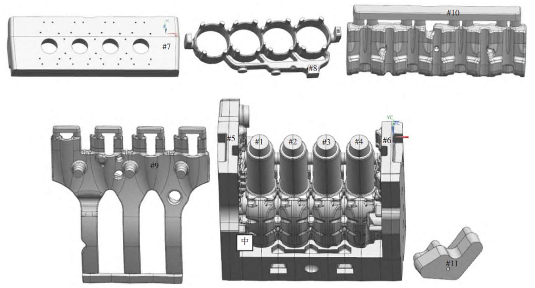
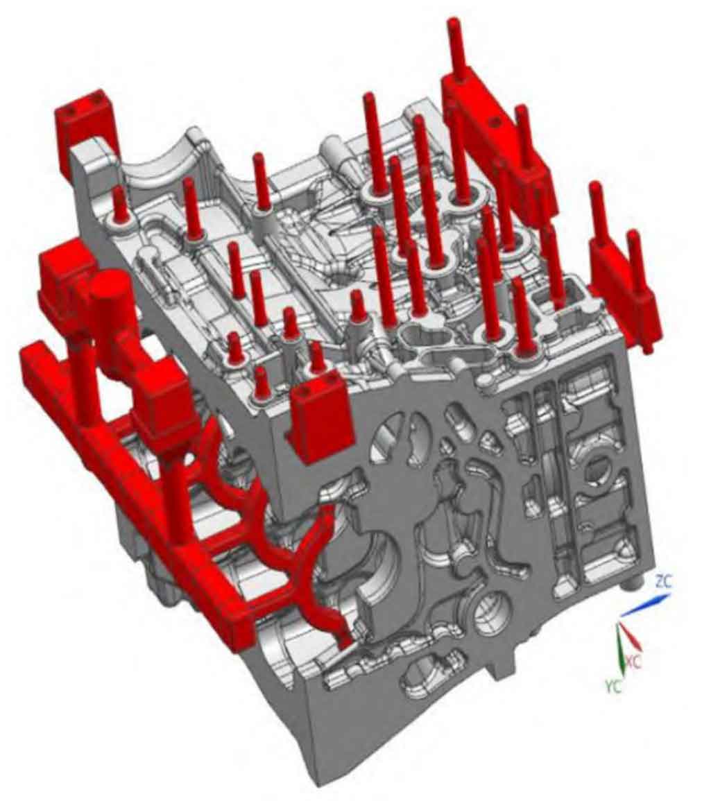
Analyze the structure of the casting, and the sand core in the inner cavity of the cylinder body is divided into 11 pieces for manufacturing (as shown in Figure 1): \1~\6 main side plate and \7 socket core are cold core core, and the main side plate core is assembled first for overall dip coating# 8. The water jacket and water channel are made into an integral sand core, and the coated sand hot core is made into a core# 9. #11 oil duct and oil passage small sand core, the arc structure of oil duct sand core is easy to deform, and it is difficult to lower the core, so the overall frame design is adopted, which is convenient for the storage, transportation and assembly of sand core, and the coated sand hot core is used for core making# 10. The tappet chamber sand core is thick and made of low-cost furan resin sand. In order to ensure the drying and thorough drying of the coating, except for the overall dip coating of the main side plate, other sand cores are combined with the main side plate core after being coated separately. During the circulation of each process, the main side plate core is always stored vertically until the lower core section. The lower core clamp uses the cylinder to turn the sand core 90 degrees and then translate the whole group of sand cores into the sand mold. The semi closed tundish pouring system is adopted, and the sprue ratio is Σ F straight: Σ F horizontal: Σ F inside =1.1:1.4:1. In order to ensure the tensile strength of the main shaft bolt position body, the iron inlet is designed to avoid the machining surface of the main bearing seat (as shown in Figure 2). Overflow exhaust risers are designed on the top and front and rear end faces of the cylinder block, and circular exhaust risers are designed at other positions. The total exhaust area is 1.7 times the iron inlet area.

Molten iron is smelted in a 10 T medium frequency induction furnace. The chemical composition of molten iron is controlled as follows: w (c) 3.3%~3.4%, w (SI) 1.8%~1.9%, w (s) 0.08%~0.09%, w (MN) 0.8%~0.9%, w (P) ≤ 0.05%, w (Cu) 0.5%~0.6%, w (CR) <0.3%~0.35%, w (MO) 0.3%~0.4%, w (SN) 0.045%~0.05%. Pouring temperature: 1400~1430 ℃.
2.Casting process test
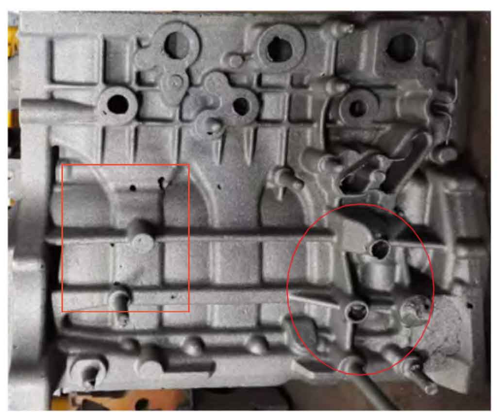
Five castings were debugged and verified for the first time. The pouring time was 35~40 S. all five castings were scrapped due to pore defects. The defects are mainly distributed on some bosses of the casting, the round exhaust riser is short, incomplete or hollow, the top is smooth, and there is suffocation. At the same time, there are a lot of air hole defects in the upper box, which are mainly distributed in the oil duct, boss and stiffener (as shown in Figure 3). Dissect the defect parts one by one, and there are mostly isolated large pores under the surface of the casting. The inner wall of the pores is smooth, and local parts are blue or dark, indicating that the surface is oxidized.

