
1.Modeling design
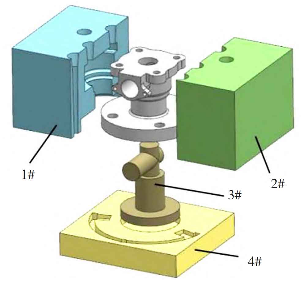
According to the current casting process technology, it is decided to adopt the precision core assembly molding of cold box with high dimensional accuracy and good surface quality, and the core is made manually without the need for sand box fixation. According to the structure of the water valve, the sand core is designed, and the analysis shows that the external shape of the water valve is symmetrical about the vertical center. With the vertical center as the parting surface, 1 # and 2 # sand cores are molded. 1 # and 2 # sand cores can be taken out from the left and right sides smoothly, and the shape of the sand core is complete. The 3 # sand core is obtained from the internal cavity structure of the water valve. In order to facilitate the modeling of the runner and the installation and fixation of the 3 # core, the bottom of the water valve is selected as the parting surface, and the 4 # sand core is designed. The shape and location of each sand core are shown in Figure 1.
2.Pouring and feeding system design
By analyzing the structure of ball valve, riser must be set for shrinkage of stainless steel liquid metal pouring. If horizontal pouring is adopted from the side, riser setting is difficult, and it is difficult to eliminate riser after pouring. After comprehensive analysis, it was decided to adopt stable pouring at the bottom. The design of runner and ingate is convenient for modeling at the parting surface. The design of the entire gating system is shown in Figure 2.
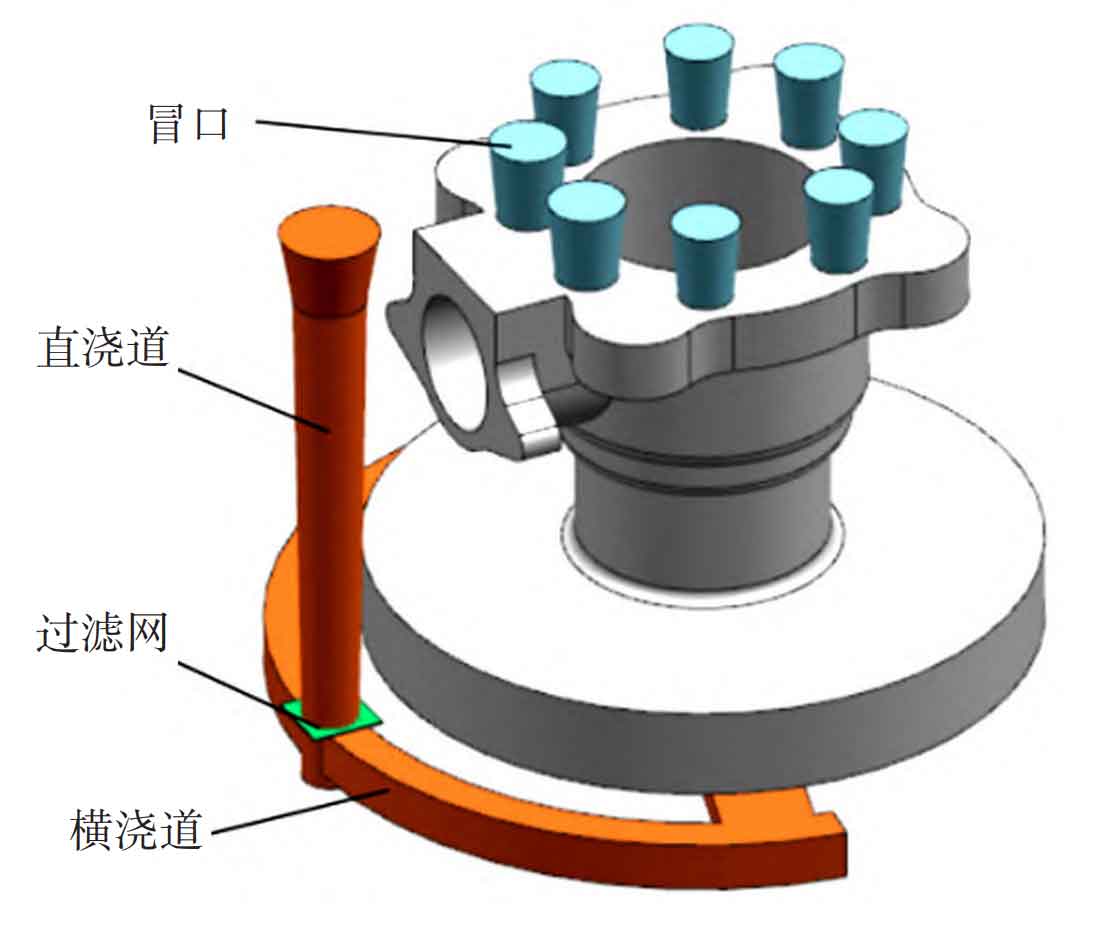
A filter screen is set at the junction of the sprue and the runner to fully prevent slag, reduce the impact of metal liquid on the sand core and avoid sand removal. The casting filling sequence is from bottom to top, so a riser is set at the top of the casting. The pouring temperature of stainless steel 304 was determined to be 1 540 ℃. The pouring temperature, cooling time and holding time were strictly controlled during the actual pouring process; At the same time, the equipment runs smoothly, and the sand core precision is strictly required, which ensures the quality of castings. The section area ratio of water valve runner is determined to be Σ F direct: Σ F horizontal: Σ F internal=1 ∶ 2 ∶ 2, and the table shows the length and section area of each runner.
| Sprue | Runner/single | Ingate/single | |
| Section area/cm^2 | 1.4 | 1.4 | 1.5 |
| Length/cm | 14.4 | 10.5 | 2.4 |