
In my extensive work within the field of metal casting, I have dedicated significant effort to the advanced design and optimization of processes for critical sand casting products. This article details my firsthand experience and methodology in developing a robust sand casting process for an automobile cushion block, a quintessential sand casting product that serves as a vital vibration-damping element in automotive transmission systems. The demand for such high-integrity sand casting products is ever-increasing, requiring meticulous design to prevent defects like shrinkage porosity, cold shuts, and misruns, all while ensuring mechanical strength under dynamic loads.
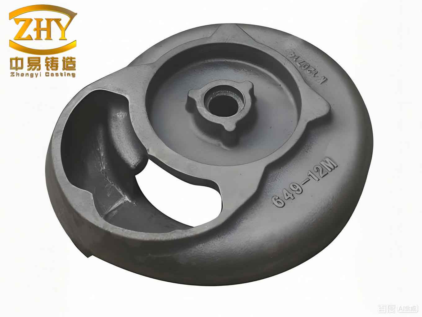
The foundation of any successful casting project lies in a thorough analysis of the component. The cushion block, with overall dimensions of 259 mm × 179 mm × 102 mm and a net weight of 7.4 kg, is a plate-like sand casting product characterized by a relatively symmetrical structure. It features multiple internal cavities, ribs, and through-holes. Its average wall thickness is 8.8 mm, with a minimum of 8 mm and a maximum of 18 mm. The geometry includes two primary cylindrical cavities surrounded by nine reinforcing ribs, each 8 mm thick, which enhance structural integrity and provide sealing. This complexity immediately highlighted the challenges inherent in producing such sand casting products, particularly concerning mold assembly and metal flow.
Material selection is paramount for the functional performance of sand casting products. I chose QT450-10 ductile iron for this cushion block due to its excellent combination of strength, ductility, and damping capacity—properties essential for automotive applications. The material was melted using a cupola-induction furnace duplex process. The chemical composition requirements I adhered to are summarized in the table below, which is critical for achieving the desired matrix structure and mechanical properties in the final sand casting product.
| Element | Min | Max | Typical Target |
|---|---|---|---|
| Carbon (C) | 3.70 | 4.00 | 3.85 |
| Silicon (Si) | 2.15 | 2.93 | 2.50 |
| Manganese (Mn) | 0.46 | 0.66 | 0.55 |
| Phosphorus (P) | – | 0.035 | 0.030 |
| Sulfur (S) | – | 0.016 | 0.012 |
| Magnesium (Mg) | 0.027 | 0.050 | 0.040 |
| Rare Earth (RE) | 0.026 | 0.043 | 0.035 |
My initial casting feasibility analysis focused on the manufacturability of this sand casting product. A key rule is ensuring the section thickness is above the minimum required for the metal to fill the mold completely. For ductile iron sand casting products of this size, the minimum feasible wall thickness typically falls between 4 mm and 8 mm. Given that the smallest wall in this design was 8 mm, it satisfied this fundamental criterion. The presence of ribs also required evaluation; their thickness must be less than or equal to the adjoining wall thickness to avoid hot spots. All ribs were 8 mm thick, congruent with the minimum wall, thus not necessitating redesign. The casting process selected was green sand molding, but for the intricate cores, I opted for furan resin no-bake sand due to its superior dimensional accuracy and collapsibility, which is often beneficial for complex sand casting products.
The core of my process design involved determining the optimal parting plane and pouring position. This is a critical decision point that affects the quality, cost, and yield of sand casting products. After evaluating several schemes, I established the parting plane to coincide with the bottom faces of the two main cylindrical cavities. This orientation placed the critical, non-machined sealing surfaces in the drag (lower mold half), thereby minimizing defects on these functional areas. The cope (upper mold half) contained the more irregular top surface with protruding features. Pouring position was set as bottom-gating to promote tranquil mold filling, reduce oxide formation, and minimize turbulence—a common strategy for quality-sensitive sand casting products. The gating system was designed as a bottom-pouring, overlap type with a trapezoidal cross-section for the runner and flat-tapered ingates. A pouring basin, sprue well with a filter (mesh size 2.5 mm × 2.5 mm), and slag traps at the runner ends were incorporated to manage metal quality.
Establishing precise casting allowances and parameters is essential for the dimensional accuracy of machined sand casting products. Based on the casting tolerance grade CT11 and the specific machining requirements for different faces, I assigned machining allowances as follows: 1.5 mm for the bottom sealing faces, 2.0 mm for the top face, and 0.5 mm for certain side faces. The patternmaker’s shrinkage allowance for this ductile iron sand casting product was set at 0.8%, a value derived from empirical data for this material and section size. The draft angle, crucial for pattern extraction in sand casting processes, was applied at 0°35′. These parameters can be interrelated; for instance, the final as-cast dimension (L_casting) can be estimated from the pattern dimension (L_pattern) using the shrinkage factor:
$$ L_{\text{casting}} = L_{\text{pattern}} \times (1 – \text{Shrinkage Allowance}) $$
For a pattern dimension of 100 mm, the expected casting size would be $$ L_{\text{casting}} = 100 \times (1 – 0.008) = 99.2 \text{ mm}. $$
The internal geometry of this sand casting product necessitated a sophisticated core assembly. I designed a system of five individual sand cores to form the cavities and undercuts. This segmented approach simplified core manufacturing and improved dimensional control. Cores #1, #2, and #3 were positioned in a single plane and located relative to each other via integrally molded alignment pins. Cores #4 and #5 were vertically located using step features in the core prints. Ensuring proper venting of these cores is vital to prevent gas defects in sand casting products. Vent channels were incorporated into all cores, primarily venting through the top surfaces and, for some, through the sides into the mold wall. The core assembly, devoid of internal chills due to their small volume, was a testament to the precision achievable in complex sand casting products.
With the initial process designed, I employed numerical simulation using AnyCasting software to virtually assess and refine the process before any metal was poured—a modern imperative for optimizing sand casting products. The model, encompassing one casting from the two-cavity mold, was meshed, and boundary conditions were set. The pouring temperature was 1,350°C, and the interfacial heat transfer coefficient between the metal and the resin sand mold was defined as 0.1 W/(m²·°C). The filling analysis showed a total fill time of approximately 4.01 seconds, with a smooth, progressive front free of excessive turbulence, validating the bottom-gating design.
The solidification analysis, however, revealed areas for improvement—a common step in perfecting processes for sand casting products. The temperature gradient and the residual liquid modulus (a predictor of shrinkage defects) indicated that while the outer walls solidified first, several isolated thermal centers, or hot spots, remained in the thicker sections at the base of the internal cylinders and in some junction areas. These regions, being the last to solidify, were susceptible to shrinkage porosity. The potential defect volume was initially calculated to be around 0.18% of the total casting volume. The solidification sequence can be partially described by Chvorinov’s rule, where the solidification time (t) for a section is proportional to the square of its volume-to-surface area ratio (modulus, M):
$$ t = k \cdot M^n = k \cdot \left( \frac{V}{A} \right)^n $$
where \( k \) is a constant dependent on mold material and metal properties, and \( n \) is typically around 2. Areas with a higher modulus solidify slower, creating the need for controlled directional solidification towards a feeder.
To engineer a sound sand casting product, I implemented a combination of risers (feeders) and chills to modify the solidification pattern. Nine small cylindrical risers, each 14.4 mm in height, were placed on the top surface over the areas adjacent to the cylindrical cavities. These risers served as reservoirs of molten metal to feed shrinkage in the casting body. Furthermore, to accelerate cooling in the thick base sections and shift the thermal center upwards, I strategically placed eight external chills arranged in two circular sets. An vent was also added at the mold’s highest point to facilitate gas escape during pouring. The design principle was to establish a temperature gradient conducive to directional solidification, which can be conceptually modeled by the heat flux equation. The heat extracted by a chill (Q_chill) can be approximated by:
$$ Q_{\text{chill}} = h_{\text{chill}} \cdot A_{\text{chill}} \cdot (T_{\text{melt}} – T_{\text{chill}}) \cdot \Delta t $$
where \( h_{\text{chill}} \) is the effective heat transfer coefficient at the chill-metal interface, \( A_{\text{chill}} \) is the contact area, \( T_{\text{melt}} \) is the metal temperature, \( T_{\text{chill}} \) is the initial chill temperature, and \( \Delta t \) is the time interval.
| Parameter | Initial Design | Optimized Design | Purpose/Effect |
|---|---|---|---|
| Risers | None | 9 cylindrical risers | Provide feed metal to compensate for solidification shrinkage. |
| Chills | None | 8 external chills | Increase local cooling rate, eliminate isolated hot spots. |
| Vent | None | 1 top vent | Allow gases to escape, reducing bubble entrapment. |
| Predicted Defect Volume | ~0.18% | ~0.09% | Quantitative improvement in internal soundness. |
| Directional Solidification | Poor (random) | Good (controlled) | Ensures shrinkage moves from casting into risers. |
Re-simulating the optimized process yielded markedly better results for this sand casting product. The filling remained smooth. The solidification sequence now clearly showed a progressive solidification front moving from the chilled base areas and the outer walls towards the risers located on the top. The previously identified thermal centers were effectively eliminated. Analysis of the residual liquid modulus confirmed a significant reduction in potential shrinkage defects, with the volume fraction dropping to about 0.09%. Furthermore, the remaining at-risk zones were consolidated in locations easily removed by subsequent machining. This optimization led to a calculated casting yield (weight of sound casting / total poured weight) exceeding 90%, which is an excellent efficiency for a sand casting product of this complexity.
My hands-on experience from design through simulation to production validation underscored several critical conclusions for manufacturing high-quality sand casting products. First, a methodical approach combining fundamental casting principles with modern simulation tools is indispensable. The initial design, while sound, harbored hidden solidification issues that only simulation could reliably reveal. Second, for complex sand casting products with internal features, a segmented core design with positive location features is highly effective in achieving dimensional accuracy and preventing mold shift. Third, the synergistic use of risers and chills is a powerful technique to control solidification dynamics in sand casting products; chills can be used to create desired temperature gradients, while risers ensure adequate feeding. Finally, this case study exemplifies how targeted process optimization can dramatically enhance the internal integrity and yield of ductile iron sand casting products, ensuring they meet stringent automotive performance standards. The successful application of these principles results in reliable, cost-effective sand casting products that form the backbone of many industrial and automotive assemblies.