
The pursuit of flawless metal castings is a constant battle against various defects, with slag inclusion standing out as a particularly persistent and detrimental flaw. This defect, characterized by non-metallic impurities such as sand, eroded refractory materials, deoxidation products, or coating particles embedded within the cast structure, severely compromises the mechanical integrity, pressure tightness, and machinability of components. My extensive experience in both conventional and advanced casting methods has solidified the understanding that controlling slag inclusion is not a matter of a single silver bullet but a holistic, systematic approach encompassing every stage of the production process. The following analysis synthesizes critical methodologies from traditional sand casting and the more modern lost foam casting (LFC) process, emphasizing that rigorous procedural discipline is paramount for success. Slag inclusion prevention is the cornerstone of reliable casting production.
The fundamental mechanisms leading to slag inclusion differ between processes but share a common root: the entrainment of foreign material into the solidifying metal. In traditional green sand or resin-bonded mold casting, inclusions often originate from eroded gating system components, loose sand from poorly prepared molds, or oxidation products formed during pouring. In the Lost Foam process, the sources are distinct and notoriously challenging: the disintegration of the foam pattern and its coating. As the molten metal replaces the vaporizing polystyrene pattern, the turbulent front can tear fragments of the fragile coating or carry loose sand from the unbonded mold into the metal stream, leading to characteristic sand-based slag inclusion defects. The viscosity of the metal and the velocity of the flow are critical factors; a relationship often simplified as the probability of entrainment $P_e$ being proportional to the Reynolds number of the flow: $$P_e \propto Re = \frac{\rho v L}{\mu}$$ where $\rho$ is density, $v$ is velocity, $L$ is a characteristic length, and $\mu$ is dynamic viscosity. Higher $Re$ signifies more turbulent flow and a greater risk of defect formation.
I. Foundational Defense in Traditional Sand Casting
For critical steel castings, such as large valve bodies or gear housings, the process control must be exceptionally stringent. The procedure can be broken down into sequential, controlled stages where vigilance against slag inclusion is non-negotiable.
1.1 Mold and Core Making
The first line of defense is a robust and clean mold. Multiple vent holes are essential in both cope and drag to ensure gases escape freely, preventing back-pressure that can cause turbulence and metal penetration into the sand—a precursor to mechanical slag inclusion. The gating system must be assembled from high-quality, pre-fired ceramic tubes. The joints between these tubes must be perfectly aligned and sealed; any misalignment creates a ledge that erodes, and any gap allows sand infiltration. A core must be designed with generous venting from its underside, connected to the main mold vents. A poorly vented core can generate gas that bursts into the metal stream, carrying core sand fragments and causing sub-surface slag inclusion clusters.
1.2 Core Setting and Mold Closing
Before setting the core, the mold cavity must be meticulously cleaned via blowing and vacuuming. Applying and thoroughly drying a zircon-based alcohol paint enhances the mold surface integrity, making it more resistant to erosion. Every vent passage in the core and core print must be verified for openness. After setting, the cavity dimensions are checked against the drawing. Any core support prints (like lifting lugs) are sealed with a quick-setting sand mixture to prevent metal ingress. The cavity is then cleaned again to remove any loose material generated during core setting. This double-cleaning is crucial for slag inclusion prevention.
Closing the mold is a ceremony of checks: vent openness, cavity cleanliness, and sealing of all gaps around core prints with refractory paste. The mold must be set on a level, compacted floor with vent channels. A dedicated refractory funnel ($\phi$100mm minimum) is mandatory; a sand-formed pour cup will inevitably erode. A final check, often with a soft paper press test to verify clearances, precedes bolting the mold. All parting line seams are packed with molding sand to prevent run-out, which can draw sand into the casting.
1.3 Melting, Pouring, and Solidification Control
Metal purity is the internal defense against slag inclusion. High levels of S and P increase hot tearing susceptibility, which can open paths for slag entrapment. Inclusions like alumina or silicates act as stress concentrators. Therefore, chemistry is controlled to mid-range specifications. A kill treatment (e.g., with rare-earth silicides) is performed in the ladle, followed by argon bubbling for inclusion floatation and homogenization. The relationship between oxide inclusion floatation time and argon flow rate can be approximated by Stokes’ law, modified for bubble-assisted flotation: $$v_t = \frac{2}{9} \frac{(\rho_i – \rho_m) g r^2}{\mu} \cdot f(Q_{Ar})$$ where $v_t$ is the flotation velocity of the inclusion, $\rho_i$ and $\rho_m$ are inclusion and metal density, $r$ is the inclusion radius, and $f(Q_{Ar})$ is a function of the argon flow rate promoting collision and adhesion.
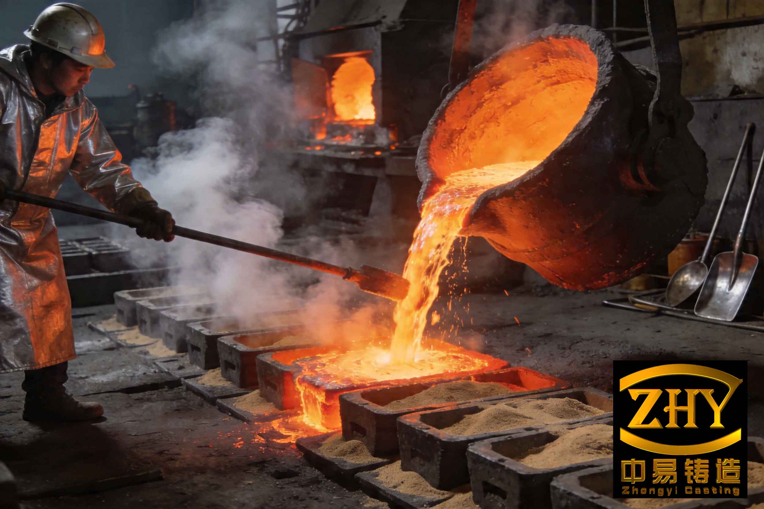
Pouring practice is a calibrated science. The ladle must be well-preheated (>700°C) to avoid thermal shock and material spalling. A bottom-pour ladle is preferred for a cleaner metal stream. The pour follows a “slow-fast-slow” regime: initial slow flow to establish a calm pool in the sprue, followed by a rapid fill to avoid mistrust, finishing with a slow feed to reduce turbulence at the end. Pouring temperature is critically monitored; for medium steel castings, a range of 1530-1550°C is typical. Too high a temperature increases metal fluidity and erosiveness, while too low a temperature hampers feeding and promotes mistrust. After the mold is full, the feeder heads are topped up at 3-minute and 5-minute intervals to compensate for volumetric shrinkage and draw any last floating slag away from the casting body, effectively acting as a slag trap.
| Process Stage | Key Control Parameter | Target/Standard | Rationale for Slag Inclusion Control |
|---|---|---|---|
| Melting | Ladle Treatment | Argon Bubbling + Rare Earth Addition | Promotes agglomeration and flotation of endogenous oxides (deoxidation products). |
| Temperature Control | Pouring Temperature | 1530 – 1550 °C | Optimizes fluidity without excessive oxide formation or mold erosion. |
| Gating System | Material & Assembly | Pre-fired Ceramic Tubes, Sealed Joints | Prevents sand wash-in and refractory erosion, a major source of exogenous slag inclusion. |
| Mold Preparation | Venting | Multiple vents in cope, drag, and core prints | Prevents gas pressure build-up that can cause sand boil and metal penetration. |
| Pouring Practice | Sequence & Feeder Management | Slow-Fast-Slow; Timed feeder topping | Minimizes turbulence; feeders act as final slag traps. |
II. The Distinct Challenge of Slag Inclusion in Lost Foam Casting
While traditional casting fights exogenous sand and refractory slag inclusion, Lost Foam Casting (LFC) battles a unique set of adversaries stemming from the process itself. The “sand inclusion” or “bead” defect in LFC is so prevalent it can be considered the archetypal slag inclusion issue for the process. It manifests as white (silica sand) or dark gray (decomposed foam residue, coating ash) spots on machined surfaces. This defect occurs because the un-bonded dry sand mold is inherently fragile, and the advancing metal front is directly interacting with the decomposing pattern and its coating.
2.1 Root Causes: A System View
The primary failure points leading to LFC slag inclusion are coating integrity and gating system sealing. The coating layer on the foam pattern has a dual mission: to provide a barrier between the metal and the sand, and to allow gaseous decomposition products to escape. If this coating cracks, delaminates, or has weak spots—especially at glued joints between the pattern and the gating system—loose sand is instantly available to be entrained by the incoming metal. The high velocity and erosive force of the metal stream during filling can directly scour off coating fragments, which then become inclusions. Furthermore, insufficient coating strength or refractory quality can lead to full penetration, where metal invades the sand bed, creating a different but related defect. The pressure differential driving metal flow, often aided by vacuum, can exacerbate this if the coating fails. The force $F_{erode}$ on a coating fragment can be related to the dynamic pressure of the flow: $$F_{erode} \propto \frac{1}{2} \rho v^2 A_c$$ where $A_c$ is the cross-sectional area of the fragment exposed to the flow.
2.2 A Seven-Point Strategy for Lost Foam Casting
Eliminating slag inclusion in LFC requires a multi-pronged attack focused on creating and maintaining a perfect, robust interface between the metal and the sand throughout the process.
1. Coating Formulation and Application: The coating is the most critical element. It must possess high green strength to survive pattern handling and vibration compaction without cracking, and high hot strength to resist metal冲刷 during pouring. Its permeability must be balanced—high enough to allow gas escape but low enough to prevent metal penetration. The coating on the gating system often requires even higher refractory properties than on the casting itself, as it withstands metal contact for a longer duration. Uniform application thickness, particularly at joints and corners, is mandatory.
2. Rigorous Pattern Assembly and Handling: Every glued seam on the pattern cluster (pattern + gating) is a potential failure point. These joints must be reinforced, sometimes with extra coating layers or external fiber mesh. The cluster must be handled with care to prevent coating damage. Any observed crack or peel before molding renders the cluster unusable.
3. Controlled Mold Filling and Vibration: The molding procedure is delicate. The pattern cluster must be placed gently on the base sand, not dropped. Initial backfilling should be done with a soft sand stream, not a direct, abrasive pour. Vibration starts at low amplitude to settle sand gently around the pattern, preventing coating distortion, and only increases to full amplitude once the pattern is fully supported. The sprue must be kept perfectly vertical and sealed at the top to prevent sand fall-in.
4. Optimized Pouring Parameters: The triad of pouring temperature, pouring time, and vacuum level is interconnected. Excessive vacuum increases metal velocity, raising the erosive force $F_{erode}$ on the coating. A high pouring temperature, while improving fluidity, can degrade the coating faster. The goal is to find the minimum parameters that ensure complete fill. For typical iron castings, a vacuum of 0.025-0.040 MPa, a pouring temperature just above the liquidus (e.g., 1380-1420°C for gray iron), and a controlled pour time (e.g., 12-20s for a medium casting) are common targets.
5. In-Mold Filtration and Slag Trapping: Incorporating ceramic foam filters in the gating system is a highly effective, albeit added-cost, strategy. The filter not only strains out entrained coating and sand particles but also laminates the flow, reducing turbulence downstream. The filtration efficiency $\eta$ for particles larger than the filter pore size $d_p$ is often very high: $$\eta \approx 1 – \exp(-k \cdot L_f)$$ where $k$ is a capture coefficient and $L_f$ is the filter thickness. Additionally, designing blind risers or slag traps at the end of the flow path or in the gating system can collect the last, dirtiest metal.
6. Sand Granularity Control: The sand itself plays a role. Sand that is too fine can lead to poor permeability and gas defects, while sand that is too coarse is more easily entrained and leads to larger, more visible slag inclusion defects. A 30/50 mesh (medium-coarse) silica sand is a typical standard for iron LFC, providing a good balance.
7. Metal Quality and Treatment: As with traditional casting, clean metal is essential. Proper melting, slagging, and holding practices to minimize endogenous oxides reduce the total inclusion load. For critical applications, ladle treatment and filtration are combined for maximum cleanness.
3. Controlled Mold Filling and Vibration: The molding procedure is delicate. The pattern cluster must be placed gently on the base sand, not dropped. Initial backfilling should be done with a soft sand stream, not a direct, abrasive pour. Vibration starts at low amplitude to settle sand gently around the pattern, preventing coating distortion, and only increases to full amplitude once the pattern is fully supported. The sprue must be kept perfectly vertical and sealed at the top to prevent sand fall-in.
4. Optimized Pouring Parameters: The triad of pouring temperature, pouring time, and vacuum level is interconnected. Excessive vacuum increases metal velocity, raising the erosive force $F_{erode}$ on the coating. A high pouring temperature, while improving fluidity, can degrade the coating faster. The goal is to find the minimum parameters that ensure complete fill. For typical iron castings, a vacuum of 0.025-0.040 MPa, a pouring temperature just above the liquidus (e.g., 1380-1420°C for gray iron), and a controlled pour time (e.g., 12-20s for a medium casting) are common targets.
5. In-Mold Filtration and Slag Trapping: Incorporating ceramic foam filters in the gating system is a highly effective, albeit added-cost, strategy. The filter not only strains out entrained coating and sand particles but also laminates the flow, reducing turbulence downstream. The filtration efficiency $\eta$ for particles larger than the filter pore size $d_p$ is often very high: $$\eta \approx 1 – \exp(-k \cdot L_f)$$ where $k$ is a capture coefficient and $L_f$ is the filter thickness. Additionally, designing blind risers or slag traps at the end of the flow path or in the gating system can collect the last, dirtiest metal.
6. Sand Granularity Control: The sand itself plays a role. Sand that is too fine can lead to poor permeability and gas defects, while sand that is too coarse is more easily entrained and leads to larger, more visible slag inclusion defects. A 30/50 mesh (medium-coarse) silica sand is a typical standard for iron LFC, providing a good balance.
7. Metal Quality and Treatment: As with traditional casting, clean metal is essential. Proper melting, slagging, and holding practices to minimize endogenous oxides reduce the total inclusion load. For critical applications, ladle treatment and filtration are combined for maximum cleanness.
5. In-Mold Filtration and Slag Trapping: Incorporating ceramic foam filters in the gating system is a highly effective, albeit added-cost, strategy. The filter not only strains out entrained coating and sand particles but also laminates the flow, reducing turbulence downstream. The filtration efficiency $\eta$ for particles larger than the filter pore size $d_p$ is often very high: $$\eta \approx 1 – \exp(-k \cdot L_f)$$ where $k$ is a capture coefficient and $L_f$ is the filter thickness. Additionally, designing blind risers or slag traps at the end of the flow path or in the gating system can collect the last, dirtiest metal.
6. Sand Granularity Control: The sand itself plays a role. Sand that is too fine can lead to poor permeability and gas defects, while sand that is too coarse is more easily entrained and leads to larger, more visible slag inclusion defects. A 30/50 mesh (medium-coarse) silica sand is a typical standard for iron LFC, providing a good balance.
7. Metal Quality and Treatment: As with traditional casting, clean metal is essential. Proper melting, slagging, and holding practices to minimize endogenous oxides reduce the total inclusion load. For critical applications, ladle treatment and filtration are combined for maximum cleanness.
7. Metal Quality and Treatment: As with traditional casting, clean metal is essential. Proper melting, slagging, and holding practices to minimize endogenous oxides reduce the total inclusion load. For critical applications, ladle treatment and filtration are combined for maximum cleanness.
| Countermeasure Category | Specific Action | Primary Effect on Slag Inclusion Mechanism | Key Consideration |
|---|---|---|---|
| Barrier Integrity | High-Strength Coating | Prevents coating fracture and sand wash-in at the metal front. | Balance between strength, permeability, and application thickness. |
| Process Stability | Gentle Vibration Compaction | Prevents mechanical damage to coating during mold making. | Low-start, ramped amplitude sequence is critical. |
| Flow Control | Optimal Vacuum & Pour Rate | Reduces metal velocity and erosive force on coating. | Must be balanced with need for complete fill; avoid excess. |
| Inclusion Removal | Ceramic Foam Filtration | Physically intercepts entrained solid particles (coating, sand). | Adds cost; requires correct sizing and placement in gating. |
| Raw Material Control | Sand Grain Size (30/50 mesh) | Reduces likelihood of sand grain entrainment. | Consistent, washed sand is necessary. |
III. Synthesis and Foundational Principles
The battle against slag inclusion across both traditional and lost foam processes reveals universal principles. First, it is a defect of entrainment and entrapment. The source material—be it sand, coating, or refractory—must first be liberated or made available (through erosion, cracking, or poor practice) and then carried into the mold cavity by the metal stream. Prevention, therefore, focuses on eliminating the source and calming the carrier.
Second, the governing physical principles are rooted in fluid dynamics and materials science. The risk of forming a slag inclusion can be conceptualized as a function: $$R_{slag} = f(F_{erode}, \sigma_{coating}, C_{impurity}, t_{fill})$$ where $R_{slag}$ is the risk, $F_{erode}$ is the erosive force of the metal flow (dependent on velocity, density, viscosity), $\sigma_{coating}$ is the strength of the interfacial barrier (coating or mold surface), $C_{impurity}$ is the concentration of potential inclusion material in/on the mold, and $t_{fill}$ is the fill time. The goal of all the aforementioned strategies is to minimize $F_{erode}$ and $C_{impurity}$ while maximizing $\sigma_{coating}$.
Finally, and perhaps most critically, the best technical knowledge is futile without impeccable execution. This is the realm of management and shop-floor discipline. A process is only as strong as its weakest operator on its least supervised shift. The “three-parts technology, seven-parts management” axiom holds profoundly true in foundry work. Consistent training, clear standard operating procedures, empowered quality checks at each station, and a culture that values meticulous detail over rushed output are the intangible yet essential elements that bind all the technical strategies together. Preventing slag inclusion is a testament to a foundry’s overall systematic excellence, where engineering knowledge and human diligence merge to produce integrity, both in the metal and in the process itself.