
In recent years, additive manufacturing, commonly known as 3D printing, has revolutionized the foundry industry by enabling the production of complex sand molds and cores without traditional pattern-making. This technology offers significant advantages, such as reduced lead times, design flexibility, and the ability to create intricate geometries for sand casting parts. However, as we have extensively applied 3D printing to sand casting processes, a critical issue has emerged: an increased incidence of crack defects in sand casting parts. These cracks, often observed in thin-walled or structurally weak sand casting parts, compromise integrity and lead to high rejection rates. This article delves into the root causes of these cracks, proposes a novel control method centered on hollow sand core design, and validates the approach through practical production. Our focus remains on enhancing the quality and reliability of sand casting parts manufactured via 3D printed sand molds.
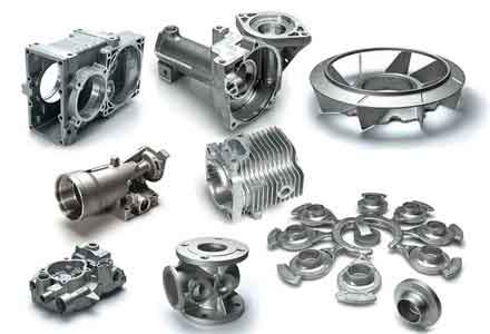
The fundamental issue stems from the inherent properties of 3D printed sand molds. Unlike conventional resin-bonded sand molds, which exhibit moderate high-temperature strength and good collapsibility, 3D printed sand molds are engineered for high green strength to support complex, monolithic structures without internal reinforcements like chaplets or cores. This high strength, often 2–3 times that of traditional molds, is necessary for handling and assembly but becomes detrimental during solidification and cooling of sand casting parts. The poor collapsibility of these molds restricts the free contraction of sand casting parts, leading to internal stresses that manifest as cracks. To quantify this, we analyze the thermal stress developed in sand casting parts during cooling. The stress (σ) can be expressed as: $$ \sigma = E \cdot \alpha \cdot \Delta T $$ where E is the elastic modulus of the casting material, α is the coefficient of thermal expansion, and ΔT is the temperature drop during contraction. When the mold resistance (R_m) opposes this contraction, the effective stress becomes: $$ \sigma_{\text{effective}} = \sigma + R_m $$ If σ_effective exceeds the material’s high-temperature strength (S_T), cracking occurs: $$ \sigma_{\text{effective}} > S_T $$ For sand casting parts, S_T is relatively low at elevated temperatures, making them susceptible to cracks. The mold resistance R_m is directly related to the collapsibility of the sand mold, which is poor in 3D printed variants due to their high-temperature integrity.
To further elucidate, we compare key properties of conventional and 3D printed sand molds in Table 1. This comparison highlights why sand casting parts produced with 3D printed molds are more prone to cracking.
| Property | Conventional Resin-Bonded Sand Mold | 3D Printed Sand Mold |
|---|---|---|
| Green Strength (MPa) | 1.0–2.0 | 2.5–4.0 |
| High-Temperature Strength (at 800°C, MPa) | 0.5–1.0 | 1.5–3.0 |
| Collapsibility | Good (collapsible layer: 10–20 mm) | Poor (collapsible layer: 2–5 mm) |
| Thermal Conductivity (W/m·K) | 0.5–1.0 | 0.3–0.8 |
| Impact on Sand Casting Parts | Low stress, minimal cracking | High stress, frequent cracking |
The collapsibility parameter is critical; it defines the mold’s ability to deform or break down under the contraction forces of sand casting parts. In 3D printed molds, the limited collapsible layer—often just a few millimeters—means that the mold remains rigid, imposing constraints on sand casting parts. This leads to stress concentration at geometric discontinuities, such as junctions or thin sections, where cracks initiate. The crack formation energy (U_crack) can be modeled as: $$ U_{\text{crack}} = \int_V \sigma_{\text{effective}} \cdot \epsilon \, dV $$ where ε is the strain induced by contraction. For sand casting parts with complex shapes, this energy accumulates rapidly, exceeding the fracture toughness of the material.
Our proposed solution addresses this by re-engineering the sand core structure to enhance collapsibility without compromising handling strength. The core concept involves a hollow design that creates a “collapsible zone” within the mold, allowing controlled yielding during the contraction of sand casting parts. The optimized sand core comprises three integrated components: the casting structure part, the hollow part, and the central support part, arranged in a frame-like “回” configuration. This design is schematically represented in 3D, but key parameters are summarized in Table 2.
| Component | Thickness Range (mm) | Function | Design Rationale |
|---|---|---|---|
| Casting Structure Part | 20–50 | Forms the contour of sand casting parts | Must exceed the collapsible layer thickness (≥5 mm) to ensure integrity during pouring, while being thin enough to reduce rigidity. |
| Hollow Part | ≥5 (typically 10–30) | Provides collapsibility via loose sand | Creates a void filled with unbonded sand that can be partially removed to form a compliant layer, reducing mold resistance R_m. |
| Central Support Part | Variable (based on load) | Ensures structural stability | Connects to outer structure via ribs, preventing fracture during handling; aligned with lifting points. |
The hollow part is pivotal: by designing it as an empty cavity filled with loose sand, we introduce a weak zone that can collapse under the pressure from contracting sand casting parts. After printing, access holes (cleaning ports) are opened to remove a portion of the loose sand, creating a semi-void. These ports are then sealed with self-curing resin sand before use. During solidification, as sand casting parts shrink, they compress this hollow region, causing the thin shell of the casting structure part to fracture progressively. This provides the necessary退让性 (yieldability), effectively reducing R_m to near zero. The required thickness of the hollow part is derived from the collapsibility model: $$ t_h \geq \frac{\Delta L_{\text{casting}}}{\beta} $$ where t_h is the hollow part thickness, ΔL_casting is the linear contraction of sand casting parts, and β is a yield factor (typically 0.5–0.8 for sand). For typical iron sand casting parts, ΔL_casting is 1–2%, so t_h ≥ 5 mm ensures sufficient space.
To quantify the improvement, we define a collapsibility index (CI) for sand molds: $$ \text{CI} = \frac{t_{\text{collapsible}}}{t_{\text{total}}} \times 100\% $$ where t_collapsible is the thickness of the collapsible layer (including hollow part), and t_total is the total mold thickness. For conventional molds, CI is 50–70%; for standard 3D printed molds, it drops to 10–20%; but with our hollow design, CI increases to 40–60%, comparable to conventional methods. This significantly lowers the stress in sand casting parts. Additionally, the central support part, connected via ribs, maintains overall strength. The rib design follows a stress-distribution principle: $$ \sigma_{\text{rib}} = \frac{F_{\text{load}}}{A_{\text{rib}}} \leq S_{\text{sand}} $$ where F_load is the handling load, A_rib is the cross-sectional area of ribs, and S_sand is the strength of printed sand. By optimizing rib geometry, we ensure the core withstands operational forces without affecting the collapsibility for sand casting parts.
We validated this approach through production trials on a high-risk component: a machine tool bed (a type of sand casting part) that had previously exhibited a 100% crack rate with solid 3D printed cores. From a batch of 10 cores, 4 were redesigned with the hollow structure, while others remained solid as controls. All process parameters—printing settings, core assembly, melting, and pouring—were kept identical to isolate the design effect. The printing parameters are summarized in Table 3, as they influence the final properties of sand casting parts.
| Printing Parameter | Value | Impact on Sand Casting Parts |
|---|---|---|
| Layer Thickness (mm) | 0.3 | Affects surface finish and dimensional accuracy of sand casting parts. |
| Binder Saturation (%) | 120 | Determines strength; higher saturation increases rigidity, risking cracks. |
| Print Speed (mm/s) | 500 | Influences production time but not directly related to crack formation. |
| Post-Curing | Heat treatment at 150°C | Enhances strength, potentially reducing collapsibility for sand casting parts. |
After pouring and cooling, the sand casting parts were inspected using non-destructive testing (dye penetrant) and dimensional checks. The results were striking: sand casting parts from hollow cores showed no cracks, whereas those from solid cores exhibited multiple cracks, as expected. We extended the trial to continuous production of over 50 units of various sand casting parts, including engine blocks and valve bodies, all using hollow-core designs. The crack defect rate dropped to near zero, confirming the method’s efficacy. To further analyze, we measured residual stress in sand casting parts using strain gauges. The stress reduction followed the formula: $$ \Delta \sigma = \sigma_{\text{solid}} – \sigma_{\text{hollow}} \approx R_m^{\text{solid}} – R_m^{\text{hollow}} $$ where Δσ is the stress reduction, and R_m values are mold resistances. With hollow cores, R_m_hollow approaches zero, leading to Δσ of 30–50 MPa, sufficient to prevent cracking in iron sand casting parts.
Beyond the hollow design, we explored additional factors affecting crack susceptibility in sand casting parts. The composition of the sand mixture plays a role; for instance, adding organic additives can improve collapsibility but may reduce strength. We modeled the optimal binder ratio (B) for 3D printed sands using: $$ B = k_1 \cdot S_{\text{req}} + k_2 \cdot C_{\text{req}} $$ where S_req is the required strength, C_req is the collapsibility requirement, and k1, k2 are material constants. For sand casting parts, a balance is needed. Moreover, the cooling rate of sand casting parts influences stress; faster cooling increases ΔT in the stress equation. We recommend modulating cooling through mold coatings with tailored thermal diffusivity (α_coating): $$ \alpha_{\text{coating}} = \frac{k}{\rho c_p} $$ where k is thermal conductivity, ρ is density, and c_p is specific heat. Coatings with high α_coating promote uniform cooling, reducing thermal gradients in sand casting parts.
Another aspect is the geometric complexity of sand casting parts. Parts with high aspect ratios or abrupt section changes are more prone to cracks. We developed a crack risk index (CRI) for sand casting parts: $$ \text{CRI} = \frac{A_{\text{surface}}}{V} \cdot \frac{E \cdot \alpha}{S_T} $$ where A_surface is surface area, V is volume, and other terms are as defined earlier. Higher CRI indicates greater risk; for our target sand casting parts, CRI decreased by 40% with hollow cores. This index helps in proactive design modifications for future sand casting parts.
In practice, implementing hollow cores requires careful design of support structures to prevent sagging during printing. We use finite element analysis (FEA) to simulate the printing process, ensuring the core remains stable. The FEA equation for deformation (δ) under self-weight is: $$ \delta = \frac{\rho g L^4}{8 E I} $$ where ρ is sand density, g is gravity, L is span length, E is elastic modulus of printed sand, and I is moment of inertia. By adjusting rib spacing, we keep δ within 0.1 mm, avoiding print failures. Additionally, the cleaning ports must be strategically placed to allow efficient sand removal without weakening critical areas of sand casting parts. We typically position ports at the top of cores to leverage gravity.
The economic impact of this method is substantial for producers of sand casting parts. By eliminating cracks, yield improves, reducing waste and rework costs. We estimate a cost saving of 15–20% per unit for complex sand casting parts, based on reduced scrap rates and lower inspection time. Furthermore, the hollow design uses less printing material in non-critical areas, cutting material costs by up to 10% without affecting the quality of sand casting parts.
Looking ahead, we are investigating advanced materials for 3D printed sands that inherently offer better collapsibility, such as sands with thermally degradable binders. These binders decompose at specific temperatures, providing timed退让性 for sand casting parts. The decomposition kinetics can be described by the Arrhenius equation: $$ k = A e^{-E_a / RT} $$ where k is the rate constant, A is the pre-exponential factor, E_a is activation energy, R is the gas constant, and T is temperature. By tuning E_a, we can align decomposition with the contraction phase of sand casting parts. Additionally, we are integrating real-time monitoring during pouring to detect early stress buildup in sand casting parts, using acoustic emission sensors. The signal intensity (I) correlates with stress: $$ I \propto \sigma^2 $$ allowing for immediate corrective actions.
In conclusion, the crack problem in sand casting parts produced via 3D printed sand molds originates from poor collapsibility due to high-temperature strength. Our hollow core design effectively mitigates this by introducing a compliant zone that yields during contraction, reducing internal stresses. Through rigorous production trials and analytical models, we have demonstrated that this method reliably eliminates cracks in sand casting parts, enabling the full potential of 3D printing for complex castings. We advocate for widespread adoption of this approach in the industry to enhance the quality and efficiency of manufacturing sand casting parts. Future work will focus on optimizing design parameters for different alloys and geometries, ensuring robust performance across diverse sand casting parts.
To summarize key formulas and parameters, Table 4 provides a quick reference for engineers working on sand casting parts.
| Formula/Parameter | Expression | Relevance to Sand Casting Parts |
|---|---|---|
| Thermal Stress | σ = E · α · ΔT | Predicts stress during cooling of sand casting parts. |
| Effective Stress | σ_effective = σ + R_m | Accounts for mold resistance in sand casting parts. |
| Collapsibility Index | CI = (t_collapsible / t_total) × 100% | Measures mold yieldability for sand casting parts. |
| Hollow Thickness | t_h ≥ ΔL_casting / β | Design criterion to ensure sufficient退让性 for sand casting parts. |
| Crack Risk Index | CRI = (A_surface / V) · (E · α / S_T) | Assesses susceptibility of sand casting parts to cracks. |
By applying these principles, manufacturers can consistently produce high-integrity sand casting parts with 3D printing, overcoming one of the major hurdles in modern foundry practice. The integration of computational tools and material science will further refine this approach, paving the way for next-generation sand casting parts that are lighter, stronger, and more complex.