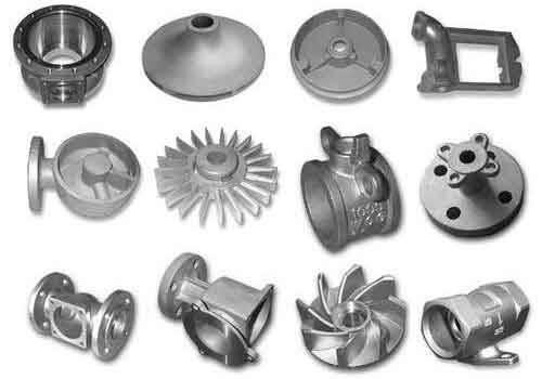
Green sand casting, utilizing clay-bonded sand molds, remains a dominant method for producing iron castings due to its cost-effectiveness and adaptability. However, defects such as sand holes, gas porosity, sand inclusions, and sand sticking frequently compromise product quality. This article systematically analyzes these defects and proposes data-driven solutions to optimize sand casting parts production.
1. Critical Defects in Green Sand Casting Parts
1.1 Sand Holes
Sand holes manifest as cavities filled with loose sand particles on casting surfaces (Fig. 1). Primary causes include:

- Insufficient mold strength: Green compression strength below 0.11 MPa
- Improper compaction: Density variations exceeding 15% across mold sections
- Core design flaws: Core seat angles < 10° or improper clearances
1.2 Gas Porosity
Gas entrapment during solidification creates spherical voids (Fig. 2), influenced by:
$$ \text{Gas Formation Potential (GFP)} = 0.8W + 1.2C $$
Where W = moisture content (%), C = coal dust content (%). Optimal GFP < 6.5.
| Parameter | Control Range |
|---|---|
| Moisture Content | 3.2–3.8% |
| Compactability (CB Value) | 32–36% |
| Permeability | 100–140 |
1.3 Sand Inclusions
Layered defects (Fig. 3) result from thermal stress in surface sand layers. Prevention requires:
$$ \text{Hot Wet Tensile Strength} \geq 2.5 \, \text{kPa} $$
1.4 Sand Sticking
Metal penetration into mold surfaces (Fig. 4) correlates with:
$$ \text{Penetration Index} = \frac{\text{AFS Fineness}}{\text{Coal Dust \%}} $$
Maintain index > 25 for sand casting parts under 50 mm wall thickness.
2. Process Optimization Strategies
2.1 Sand System Management
| Additive | Addition Rate | Function |
|---|---|---|
| Bentonite | 8–12% | Binder strength |
| Coal Dust | 4–6% | Surface finish |
| New Sand | 5–15% | Granularity control |
2.2 Mold Engineering Controls
- Compaction uniformity: Achieve ≥85 hardness on all surfaces
- Venting efficiency: Minimum 1 vent/cm² for sand casting parts >10 kg
- Core seat design: 10° taper angle with 0.5–1 mm clearance
2.3 Metallurgical Factors
Pouring parameters significantly affect defect formation:
$$ \text{Thermal Stress Factor} = \frac{T_{\text{pour}} – T_{\text{solidus}}}{t_{\text{filling}}} $$
Maintain < 150°C/s for gray iron sand casting parts.
3. Quality Improvement Metrics
| Defect Type | Pre-improvement Rate | Post-improvement Rate |
|---|---|---|
| Sand Holes | 3.2% | 1.1% |
| Gas Porosity | 2.8% | 0.9% |
| Sand Inclusions | 1.5% | 0.6% |
| Sand Sticking | 0.5% | 0.2% |
4. Advanced Process Controls
4.1 Real-time Sand Monitoring
Automated systems track key parameters:
$$ \text{Moisture Compensation} = 0.02 \times (T_{\text{sand}} – 35) $$
Where \( T_{\text{sand}} \) = sand temperature (°C)
4.2 Predictive Quality Modeling
Defect probability analysis for sand casting parts:
$$ P_{\text{defect}} = 1 – e^{-(0.5x_1 + 0.3x_2 + 0.2x_3)} $$
Where \( x_1 \) = moisture deviation (%), \( x_2 \) = permeability deviation, \( x_3 \) = CB variation
5. Economic Impact Analysis
Implementation of these measures reduced total scrap rate from 8% to 4.5%, generating annual savings exceeding $1.2 million for medium-scale foundries producing 20,000 tons of sand casting parts.
6. Future Development Trends
- AI-powered sand system optimization
- Nanocoated bentonite for enhanced strength
- IoT-enabled mold condition monitoring
Through systematic control of sand parameters, process optimization, and advanced quality management, manufacturers can significantly enhance the reliability of green sand casting parts while maintaining competitive production costs.
