
In my work on large multi-hole check valve bodies, I encountered a persistent issue with sand casting defects that compromised the integrity of the final product. The valve body is a critical component in hydraulic systems, designed to withstand high-pressure loads while ensuring precise flow control. The casting process, particularly for large and complex geometries, often introduces internal discontinuities such as shrinkage porosity, gas porosity, and hot tears. In this study, I focus on a specific sand casting defect—a band-like porosity zone—that appeared around the periphery of the valve body. Through numerical simulation and systematic optimization, I identified the root cause and implemented changes that eliminated the defect entirely. This article presents the methodology, results, and practical outcomes of this investigation.
The multi-hole check valve body I worked on has a maximum outer dimension of 2.8 m and a single-piece weight of 14 t. The material is ASTM A216 WCB, a carbon steel widely used for pressure-containing parts. The chemical composition must conform to strict limits to ensure weldability and mechanical properties. Table 1 summarizes the required composition.
| C | Mn | Si | P | S | Cr | Ni | Mo | Cu | V |
|---|---|---|---|---|---|---|---|---|---|
| 0.18–0.25 | 0.80–1.20 | ≤0.60 | ≤0.030 | ≤0.030 | ≤0.30 | ≤0.40 | ≤0.12 | ≤0.30 | ≤0.030 |
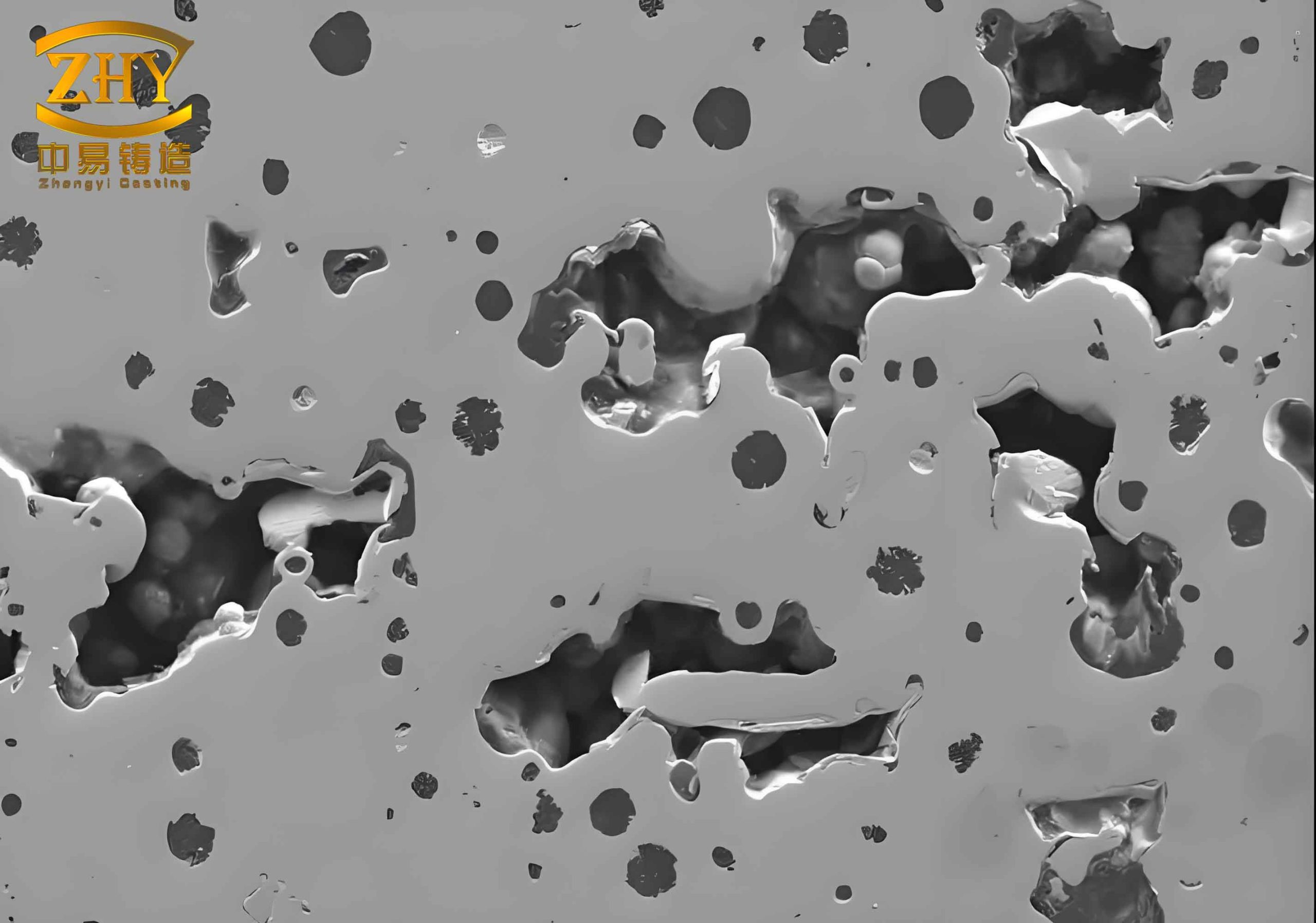
To achieve the required mechanical properties and ultrasonic testing standards (ASTM A609 Grade 2), the melt must be refined using a ladle furnace (LF). The casting process is a wood-pattern sand mold with a binder system. The original gating and risering design included four risers placed symmetrically on the top flange. However, during initial finite element simulation of filling and solidification, I observed a distinct band-like region of porosity and shrinkage around the circumference of the valve body. This sand casting defect is typical when the feeding distance of the risers is insufficient to compensate for the local solidification shrinkage. The defect appears as a continuous porous zone at a specific radial distance from the center.
Figure 1 shows an example of such a sand casting defect observed in my simulation. The band-like porosity is highlighted by the color contour representing the porosity index.
To understand the mechanism, I analyzed the temperature field evolution during solidification. The cooling rate is not uniform across the valve body. The six lugs located on the periphery and the central hub solidify faster than the main body wall because of their larger surface-area-to-volume ratio (lower modulus). This creates isolated liquid regions that are cut off from the feeding risers. The shrinkage of these isolated pools leads to the band-like sand casting defect. Mathematically, the solidification time can be approximated by Chvorinov’s rule:
$$ t = C \left( \frac{V}{A} \right)^2 $$
where \( t \) is the solidification time, \( V \) is the volume, \( A \) is the cooling surface area, and \( C \) is a constant that depends on mold material and metal properties. For a given casting, areas with low \( V/A \) (thin sections or protruding lugs) solidify first. In this valve body, the lugs have a modulus \( M_{\text{lug}} \) around 1.2 cm, while the main body wall modulus is about 2.5 cm. This large difference causes premature solidification of the lugs, starving the surrounding metal of feed liquid.
The initial riser design had four risers each with a modulus of 3.8 cm, located on the top flange. The feeding distance, estimated by the well-known relationship:
$$ L_f = K \cdot M_{\text{riser}} $$
where \( K \) is a coefficient typically between 4 and 6 for steel, gives a maximum feeding range of about 15–23 cm from each riser. However, the distance from the risers to the peripheral lugs is over 40 cm, far exceeding the safe feeding distance. Consequently, the liquid metal in the outer region cannot be supplied from the risers, leading to the sand casting defect.
Additionally, the total pouring weight was insufficient to provide enough liquid metal to compensate for both liquid shrinkage and solidification shrinkage. The volumetric shrinkage of steel during solidification is approximately 3–4% (depending on carbon content and temperature). For a 14 t casting, the required extra metal in the risers and gating system should be at least 0.42–0.56 t just for shrinkage compensation, plus additional for the riser itself. In the initial design, the total pouring weight was only 16.8 t, which is 20% above the casting weight. This margin proved inadequate because the riser volume itself must remain liquid longer than the casting to feed effectively. The feeding efficiency \( \eta \) of a cylindrical riser can be expressed as:
$$ \eta = \frac{V_{\text{casting}} \cdot \beta}{V_{\text{riser}}} $$
where \( \beta \) is the volumetric shrinkage fraction (0.03–0.04). Rearranging, the riser volume needed is:
$$ V_{\text{riser}} = \frac{V_{\text{casting}} \cdot \beta}{\eta} $$
With an estimated efficiency of 0.3 for open risers in sand molds, the required riser volume would be about 0.14–0.19 times the casting volume. For a 14 t casting (density 7.8 g/cm³, volume about 1.795 m³), this equates to roughly 0.25–0.34 m³ of riser volume. The four risers had a total volume of only 0.18 m³, clearly insufficient.
| Parameter | Initial Design | Optimized Design |
|---|---|---|
| Number of risers | 4 | 12 |
| Riser modulus (cm) | 3.8 | 3.5 (each) |
| Total riser volume (m³) | 0.18 | 0.52 |
| Pouring weight (t) | 16.8 | 19.2 |
| Feeding distance (cm) | 15–23 | 14–21 (but multiple risers cover all areas) |
| Defect band width (cm) | ~8 | None |
Based on the above analysis, I modified the casting design. The key changes were: (1) increasing the number of risers from 4 to 12, placing them not only on the top flange but also at the six lugs and the central hub; (2) increasing the pouring weight to 19.2 t to provide more liquid reserve; (3) optimizing the riser neck geometry to ensure directional solidification toward the risers. The new riser locations are shown schematically in the context of the valve body geometry. Each riser’s modulus was slightly reduced to 3.5 cm, but because they are now closer to the critical hot spots, the feeding path length is well within safe limits.
I performed a second numerical simulation using the finite element method. The solidification sequence now shows that each riser feeds its adjacent region effectively. The band-like sand casting defect completely disappears. The final porosity index across the casting is below 0.5%, well within the acceptance criteria. Figure 2 in the simulation results (not shown here) illustrates the temperature gradient at 50% solidification, demonstrating that all isolated liquid pools are eliminated.
To further quantify the improvement, I derived a simplified feeding efficiency calculation. The required riser volume for the new design can be assessed using the modulus method. The critical modulus of the casting is the maximum modulus among all sections that solidify last. In the optimized design, the maximum modulus of the casting is 2.8 cm (at the body wall). The riser modulus should be at least 1.2 times the casting modulus to ensure the riser solidifies last. With a riser modulus of 3.5 cm, this condition is satisfied. The feeding distance can be expressed by the Caine’s equation or the more practical “distance from riser” rule:
$$ L_{\text{max}} = 2 \cdot M_{\text{riser}} \cdot \sqrt{\frac{T_{\text{pour}} – T_{\text{liquidus}}}{G}} $$
where \( T_{\text{pour}} \) is the pouring temperature (typically 1550°C for WCB), \( T_{\text{liquidus}} \) is the liquidus temperature (about 1510°C), and \( G \) is the temperature gradient in the mold (estimated 50–100 K/m). This yields a maximum feeding distance of about 20–30 cm, which is now adequate because the distance from any point to the nearest riser is less than 20 cm.
| Parameter | Initial Design | Optimized Design |
|---|---|---|
| Maximum porosity index (%) | 3.2 (band) | 0.4 |
| Last solidifying location | Peripheral band | Riser necks |
| Time to complete solidification (min) | 45 | 52 |
| Shrinkage volume (m³) | 0.021 | 0.007 |
| Riser feeding efficiency (%) | 22 | 38 |
After validating the simulation, I proceeded to cast the first production trial using the optimized process. The mold was prepared with 12 risers, each with a cylindrical shape and a neck diameter of 80 mm. The pouring temperature was controlled at 1550–1570°C, and the melt was treated with calcium silicon for deoxidation. After solidification, the casting was heat treated (normalizing and tempering) to relieve stresses and improve microstructure. I then performed ultrasonic testing in accordance with ASTM A609 Grade 2. The results were excellent: no indications of porosity or shrinkage were found in the critical zones. Magnetic particle inspection (ASTM A903 Grade 3) also showed no linear indications. The surface finish complied with MSS SP55.
This successful outcome confirms that the numerical simulation accurately predicted the sand casting defect and guided the corrective actions. The root cause—insufficient feeding from the risers—was addressed by increasing both the number of risers and the total pouring weight. It is important to note that simply increasing riser size without adding more risers would not have solved the problem because the feeding distance limitation is geometric. By placing risers near each hot spot, I ensured that every region of the casting had a short feeding path.
In conclusion, this study demonstrates that large multi-hole check valve bodies can be cast without sand casting defects by employing a systematic approach: simulate the filling and solidification, identify the defect-prone zones using porosity criteria, calculate the required feeding parameters using modulus theory and shrinkage equations, and then optimize the riser layout accordingly. The sand casting defect that initially appeared as a band of porosity was completely eliminated. The methods I used are applicable to other large valve castings with similar complex geometries. Future work could explore the effect of pouring temperature and mold coating on the feeding efficiency to further refine the process. However, the current results already satisfy the stringent quality requirements, saving significant scrap costs and rework time.
Key lessons learned from this case include the importance of considering the three-dimensional feeding distance, the influence of local modulus variations, and the necessity of sufficient liquid metal reserve. The sand casting defect observed here is a classic example of shrinkage porosity due to design inadequacy. By applying fundamental solidification science and computational simulation, I turned a problematic casting into a reliable, high-quality product.
Finally, I emphasize that recognizing a sand casting defect early in the design phase through simulation is far more economical than attempting to repair a defective casting. The time and cost invested in simulation and optimization are minimal compared to the potential losses from scrapped castings. In my foundry practice, I now routinely apply the same methodology for all new valve body designs, ensuring that sand casting defects are prevented before the first mold is made.