
1 Product introduction and technical requirements
At present, China’s new urbanization process has entered a new stage of high-quality development, with central cities driving the construction of modern metropolitan areas and urban agglomerations, and continuously deepening regional coordinated development. With the continuous expansion of the volume and scale of the regional central city, it is a key transportation party to balance the uniform development of the urban plate
There is still room for further development of urban rail transit in the future. The motor shell of the urban rail transit traction system is cast and formed, the casting material is QT500-7, the main body is a thin-walled barrel structure, the contour size is 760 mm×500 mm×580 mm, the mass is about 160 kg, the wall thickness of the main body is 10 mm, and the maximum wall thickness is 90 mm. Castings require X-ray flaw detection with acceptance criteria of Level 2 for critical areas and Level 3 for non-critical areas. According to the drawings, the preliminary analysis shows that there are many isolated hot joints in the product, which are mainly distributed: (1) the contact between the inner ring rib and the barrel wall;
(2) The contact between the upper and lower mounting brackets and the barrel wall; (3) The contact between the safety support and the barrel wall; (4) The contact between the junction box and the barrel wall. The specific location and modulus value of the hot joint are analyzed and determined with the assistance of MAGMA simulation software.
2 Casting process design
2.1 Determination of typing method
There are two ways to analyze the pouring position from the product structure: (1) the axis of the barrel is placed vertically, referred to as vertical; (2) The axis of the barrel is placed parallel to the ground, referred to as flat. A large number of sand cores need to be set up vertically around the barrel wall, and the pouring system is required The system adopts the bottom injection type, the molten iron filling is stable, and the hot joint at the inner ring rib is easy to solve, but the hot joint at the installation bracket is difficult to solve; Flat along the axis of the barrel HALF parting, the number of sand cores is relatively small, and the installation bracket is hot It is easy to solve, but it is difficult to solve the hot joints at the inner ring ribs. Considering the use requirements of the product, the flat HALF parting method was finally adopted.

Fig.1 3D model of motor housing
2.2 Gating system design
After the classification method is determined, there are two schemes for the molten iron feeding mode: (1) the annular inlet cross sprue is arranged at both ends of the lower barrel, and the molten iron is fed by the flat sprue; (2) A cross sprue is arranged along the parting surface from the barrel wall, and the flat sprue method is adopted Liquid iron is fed. The first scheme has stable filling and low yield of casting process; The second scheme is prone to turbulent flow, but the process yield is high. After comprehensive consideration, the second option is adopted. The existing flask sizes are 1 000 mm× 980 mm× 480 mm for the upper type and 1 000 mm × 980 mm × for the lower type 340 mm。 One type and one piece, the gating system designs 2 inner sprues to introduce the molten iron into the cavity, and after the process plan is determined, the specific process parameters are calculated.
2.3 Application of riser and cold iron
Under the condition that no process measures such as cold iron and riser are placed, according to the calculated process parameters, the solidification process of the casting is preliminarily simulated and analyzed by MAGMA software, and the position of the hot joint and the corresponding modulus are predicted, and the solidification is simulated This is shown in Figure 2. The simulation results show that there are many large hot joints in the casting (Figure 3). Shrinkage porosity defect prediction is shown in Figure 4. According to the simulation results, combined with the technical requirements of the product, technological measures such as placing cold iron and heating and heat insulation riser at the corresponding hot joint position were taken, and the casting process scheme was preliminarily determined, as shown in Figure 5. The heating and heat preservation riser is selected according to the specification, model and the hot joint modulus of the placement part. It should be noted that after the heat insulation riser is placed, the hot joint modulus of the casting at the place will increase due to the placement of the riser. For example, as shown in Figure 6, the simulation display module at the hot joint of the upper mounting bracket is 1.6 cm, and the simulation shows that the module here is increased to 1.9 cm after the riser is set.
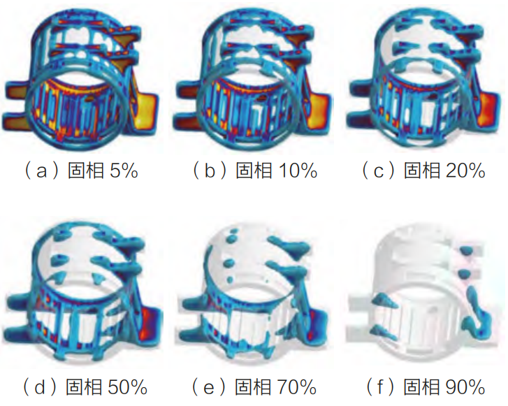
Fig.2 Solidification simulation

Fig.3 Heat node distribution
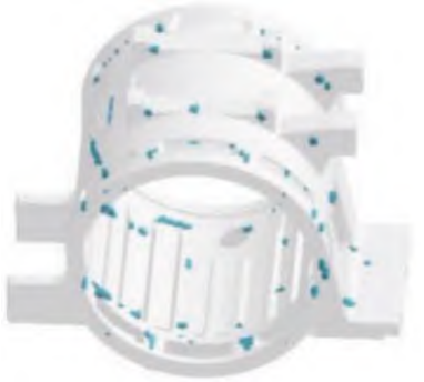
Fig.4 Shrinkage defect
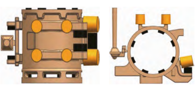
Fig.5 Casting process scheme
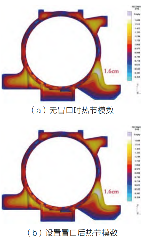
Fig.6 Modular contrast
If the selection is too small, the riser will solidify before the casting, which is easy to cause shrinkage porosity defects at the root of the riser.
3 Trial production and effect
Before trial production, the solidification process simulation analysis was carried out on the preliminarily determined casting process scheme (Figure 7). The simulation shows that the selection and placement of the riser forms a temperature gradient field from low to high, which plays a role in local sequential solidification, and the final solidification part of the casting is in the top riser, and the results show that the possibility of shrinkage and porosity defects in the casting is small. After the first trial production, X-ray inspection of the casting (Figure 8) found that there was a shrinkage defect in the contact area between the junction box and the barrel wall, which exceeded the level 3 standard for non-critical areas specified in the technical requirements and did not meet the customer’s acceptance requirements. Analyze the cause of the defect: there is an isolated liquid phase zone in this area, which is not obtained
Sufficient refueling of molten iron results in shrinkage defects.
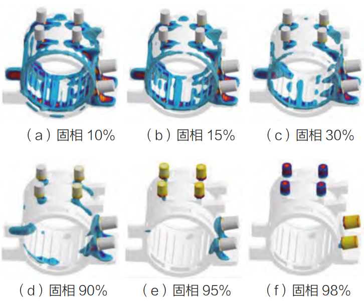
Fig.7 Solidification simulation
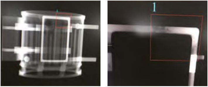
Fig.8 X-ray results
After analyzing the causes of the defects, corresponding measures were taken: two pieces of cold iron were added at the contact position between the casting junction box and the barrel wall to accelerate the solidification rate of the area, reduce the isolated liquid phase area, and reduce the shrinkage defect area.
The optimized casting process scheme is shown in Figure 9.
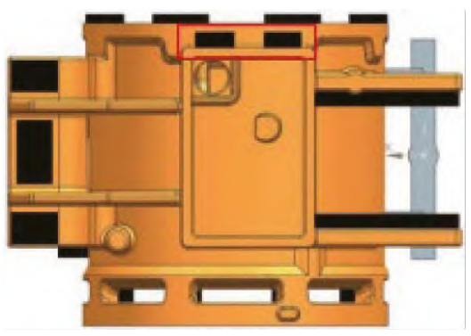
Tab.9 Chill of junction box
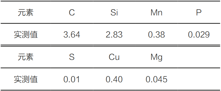
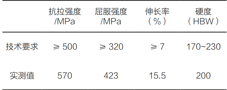
The castings were trial-produced again, and the X-ray, mechanical properties and other tests were in line with the customer’s acceptance standards, and the chemical composition of the castings and the mechanical properties of the single-cast samples were shown in Table 1 and Table 2.
Tab.1 Chemical composition of casting (mass fraction, %)
Tab.2 Mechanical property
4 Conclusion
The application of simulation software in the casting process design makes the design process simple, especially in the modulus calculation, which saves the previous cumbersome segmentation calculation, and can be directly obtained in the simulation results; In the judgment of shrinkage porosity and other casting defects When trapping, it is necessary to combine the isolated liquid phase zone that occurs during the solidification process of the molten metal, and cannot be ignored because of the small possibility of shrinkage defects, which is related to the chemical composition, pouring temperature and inoculation conditions set during the simulation.