
In my extensive experience within aerospace manufacturing, the production of high-integrity sand casting parts presents a unique set of challenges, especially when dealing with intricate geometries like double-flow channel volutes. The shift from fabricated assemblies to monolithic sand cast components is driven by the relentless pursuit of reliability, weight reduction, and performance in critical systems. This narrative details the comprehensive journey and methodologies developed to successfully sand cast a large-area, thin-walled aluminum alloy double-flow volute, a component where conventional approaches fell short. The core of this endeavor revolved around solving the fundamental issues of supporting and venting a fully enclosed, suspended annular sand core, while rigorously controlling process dynamics to ensure soundness in these demanding sand casting parts.
The volute in question, intended for a turbine cooler unit, is a paradigm of complexity. Initially, a single-flow channel design proved insufficient, and a fabricated version welded from separate castings introduced failure-prone weld seams. The decision to cast it as one integral piece from ZL114A alloy (a common Chinese designation for a high-strength aluminum casting alloy similar to A356) was pivotal. As illustrated below, the component features two concentric, spiral flow channels. The outer channel is relatively accessible, but the inner channel—forming the second flow passage—is created by a core that is almost entirely encapsulated by metal, with only four small diameter ports connecting it to the exterior. This defines it as a “fully enclosed suspended annular core.”
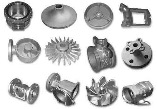
Technically, the challenges were multifaceted. First, the wall thickness separating the two flow channels was specified at a mere 1.5 mm, extending over a considerable area. The ZL114A alloy, with its relatively wide solidification range (approximately 80°C in equilibrium), exhibits poor fluidity, high hot tearing susceptibility, and a propensity for shrinkage porosity. These inherent material characteristics are particularly adversarial to the successful filling and solidification of large, thin-walled sections in sand casting parts. Second, the suspended core had to be positioned with micron-level precision to achieve uniform wall thickness and prevented from floating during metal pouring. Third, and most critically, this core, made from organic-bonded sand, would generate vast amounts of gas when heated by the 700+°C molten aluminum. Without an effective escape route, this gas would be forced into the solidifying metal, creating severe blowholes and rendering the sand casting part defective. The performance requirement of withstanding 0.4 MPa of kerosene pressure for 5 minutes without leakage made any such defect unacceptable.
The foundational innovation lay in the core support and venting system. For positioning, we abandoned rigid ceramic supports in favor of a ductile copper tube system. Four copper tubes were bent to a specific curvature and embedded into the oil-sand core (Core #2) during its manufacture. These tubes protruded through the four designated ports and were anchored into chill blocks set in the mold. This design offered multiple advantages: the copper’s melting point is higher than the aluminum’s, preventing fusion; its malleability allowed for secure mechanical interlocking with the core sand; and most importantly, the hollow tubes provided a dedicated conduit for gas evacuation. This approach is a cornerstone for manufacturing such enclosed geometry sand casting parts.
Creating the venting path within the core itself was equally ingenious. Traditional methods like poking wires or carving channels were inadequate for the annular shape. Initial trials using wax-coated cord left inconsistent channels and combustible residue. The breakthrough came from using a custom-made mold to press a continuous U-shaped wax ring. This ring was placed in the core box before sand ramming. After baking the core at 220-240°C, the wax melted and drained away, leaving behind a perfectly smooth, continuous annular gallery inside the core. This gallery connected to the four copper tubes, creating an integrated, low-resistance exhaust network for gases produced during the pour. The gas evolution rate from the decomposing binders can be conceptually modeled by an Arrhenius-type equation:
$$ \frac{dG}{dt} = A \cdot e^{-E_a/(R T(t))} $$
where \(dG/dt\) is the gas generation rate, \(A\) is a pre-exponential factor, \(E_a\) is the activation energy for binder decomposition, \(R\) is the universal gas constant, and \(T(t)\) is the time-dependent temperature at the core-metal interface. An efficient vent path must ensure the pressure \(P_g\) in the gallery remains below the metal penetration pressure \(P_m\):
$$ P_g = \frac{\dot{G} \cdot R_u \cdot T}{V_{vent} \cdot \eta} \cdot t < P_m \approx \frac{2\gamma \cos\theta}{r_{pore}} $$
Here, \(R_u\) is a gas constant, \(V_{vent}\) is the vent volume flow capacity, \(\eta\) is gas viscosity, \(\gamma\) is surface tension, \(\theta\) is contact angle, and \(r_{pore}\) is the pore radius in the metal dendrite network. The U-wax ring solution maximized \(V_{vent}\) and minimized \(P_g\).
| Category | Parameter | Value / Specification | Rationale |
|---|---|---|---|
| Component Design | Material | ZL114A (Al-Si-Mg) Alloy | High strength, weldable, but challenging casting properties. |
| Critical Wall Thickness | 1.5 mm | Defines thin-section challenge for fluidity and feeding. | |
| Major Outer Dimension | ~Ø 200 mm | Indicates the substantial size of the sand casting part. | |
| Core System | Core #2 Material | Oil-Sand (Organic Binder) | Standard for complex shapes, but high gas generation. |
| Support/Vent Method | Curved Copper Tubes (x4) & U-Wax Ring | Provides mechanical fixation and integrated gas evacuation. | |
| Core Baking Temperature | 220 – 240 °C | Optimized for curing strength and complete wax removal. | |
| Vent Channel Cross-Section | ~20 mm² (from U-ring) | Ensures sufficient flow area to prevent back-pressure. | |
| Pouring & Solidification | Pouring Temperature | 730 – 750 °C | Elevated to enhance fluidity for thin walls. |
| Pouring Strategy | Fast pour to sprue base, then slow feed for risers | Ensures rapid mold filling followed by directional solidification. | |
| Gating System Type | Multiple Ingates (≥4) | Distributes heat and metal, reduces local turbulence. | |
| Core Float Prevention | Steel Wire Pins (removed during pour) | Dynamic control to counter buoyancy until metal envelops core. | |
| Target Solidification Gradient | \( \nabla T_{local} > 10 \, ^\circ\text{C/cm} \) | Promotes feeding and reduces hot tear risk in thin sections. | |
| Post-Casting | Copper Tube Removal | Mechanical extraction + Nitric Acid etching | Exploits differential chemical stability of Al vs. Cu. |
| Core Sand Removal | Vibration + High-Pressure Water Jetting | Effective cleaning of internal, complex passages. |
With the core system designed, the overall sand casting process required meticulous dynamic control. We employed a multi-pronged strategy. First, precision was ensured through dedicated gauges. A core-making template guaranteed the suspended core’s dimensions were perfect before baking. A separate core-setting template was used after the mold was assembled to physically check the wall thickness around the entire flow channel cavity before closing the mold. This hands-on verification was crucial for sand casting parts with tight tolerances like this volute.
The gating and risering system was designed to tackle the alloy’s poor fluidity and tendency for shrinkage. We implemented a system with multiple ingates arranged around the volute’s base to ensure simultaneous, rapid, and distributed filling. The thermal dynamics are critical. The heat transfer during filling must be sufficient to preclude premature freezing. A simplified energy balance at the metal front can be expressed as:
$$ \rho_m C_p \frac{\partial T}{\partial t} + \rho_m C_p \vec{v} \cdot \nabla T = \nabla \cdot (k_m \nabla T) + q_{interface} $$
where \(\rho_m\), \(C_p\), and \(k_m\) are the density, specific heat, and thermal conductivity of the molten aluminum, \(\vec{v}\) is the flow velocity, and \(q_{interface}\) represents heat loss to the mold and core. A high pouring temperature (~740°C) and fast initial fill rate increased the term \(\rho_m C_p \vec{v} \cdot \nabla T\), helping to maintain superheat across the thin sections. After the mold was filled to the base of the risers, the pouring technique shifted to a slow, hot topping-up of the risers. This maintained a strong thermal gradient, driving directional solidification from the thin walls towards the risers, which acted as feed reservoirs. The Niyama criterion, often used to predict shrinkage porosity, can be adapted for such geometries:
$$ G / \sqrt{\dot{T}} > C $$
where \(G\) is the temperature gradient, \(\dot{T}\) is the cooling rate, and \(C\) is a critical value for the alloy. Our process aimed to maximize \(G\) in the critical thin-wall zones through controlled thermal management.
The most dynamic operation during the pour was preventing core floatation. Despite the copper tube anchors, the buoyant force \(F_b\) on the core when submerged in aluminum is significant:
$$ F_b = V_{core} \cdot (\rho_{Al} – \rho_{sand}) \cdot g $$
where \(V_{core}\) is the core volume, \(\rho_{Al}\) is the density of molten aluminum (~2.38 g/cm³), \(\rho_{sand}\) is the effective density of the baked oil-sand core (~1.6 g/cm³), and \(g\) is gravity. To counter this temporarily, two steel wire pins were inserted through the mold cope to press down symmetrically on the top of the suspended core. The operator’s skill was paramount here: the pins had to be withdrawn the moment the rising metal reached their roots. Withdrawing too early would allow the core to float; too late, and the pin would freeze into the casting, creating a cold shut or leak path. This real-time, manual intervention was a vital component of quality control for these high-stakes sand casting parts.
Post-casting, the challenges shifted to extraction and cleaning. The copper tubes, having served their purpose, needed complete removal. Any residual copper could cause localized eutectic melting and overburning during the solution heat treatment of the aluminum alloy. The tubes were first pulled out mechanically. If any segment broke off inside the internal channel, we exploited electrochemistry. A concentrated nitric acid (HNO₃) solution was introduced into the passage. The reaction proceeds as:
$$ 3Cu + 8HNO_3 \rightarrow 3Cu(NO_3)_2 + 2NO + 4H_2O $$
The aluminum alloy, having a stable passive oxide layer, is largely unattacked by concentrated nitric acid, allowing selective dissolution of the copper remnants. This elegant solution ensured the integrity of the final sand casting part. The burned-out core sand was then removed using a combination of mechanical vibration and high-pressure water blasting, leaving clean, precise internal passages.
The outcomes of implementing this holistic methodology were definitive. The sand cast double-flow volutes met all dimensional specifications, including the challenging ±0.25 mm tolerance on critical features. Most importantly, they consistently passed the stringent 0.4 MPa kerosene pressure test, demonstrating mechanical soundness and leak-tight integrity. Metallographic inspection of sections revealed dense, shrinkage-free structures in the thin-wall areas, with no evidence of gas porosity or hot tears. This success underscores that even for highly complex geometries, sand casting is a viable and robust manufacturing process. The techniques developed—particularly the integrated copper tube support/U-wax ring vent system and the dynamic pouring controls—have broad applicability for other enclosed-cavity sand casting parts in aerospace and beyond.
In conclusion, the journey to perfect this double-flow volute sand casting part was an exercise in systematic problem-solving. It reinforced that success in advanced sand casting hinges on a deep understanding of the interplay between geometry, material science, and process physics. The key takeaways are: 1) Innovative core support and venting systems are not just accessories but fundamental design elements for complex sand casting parts. 2) Process parameters cannot be static; they require a philosophy of dynamic control, blending calculated design with skilled execution. 3) Post-casting operations must be considered integral to the process flow to ensure final quality. The knowledge gained significantly expands the envelope of what is considered castable, proving that with meticulous engineering, sand casting can produce monolithic, leak-proof, thin-walled components of extraordinary complexity, rivaling and often surpassing the reliability of fabricated assemblies. The future development of sand casting parts will continue to leverage such integrated approaches, combining traditional foundry wisdom with modern analytical tools and material insights.