
Sand casting is a thick-walled plate-like part with low overall height. In order to facilitate modeling, the gating system is designed to be introduced from the parting surface. Two sand casting process schemes of gating and feeding systems are designed for comparison.
(1) Scenario A
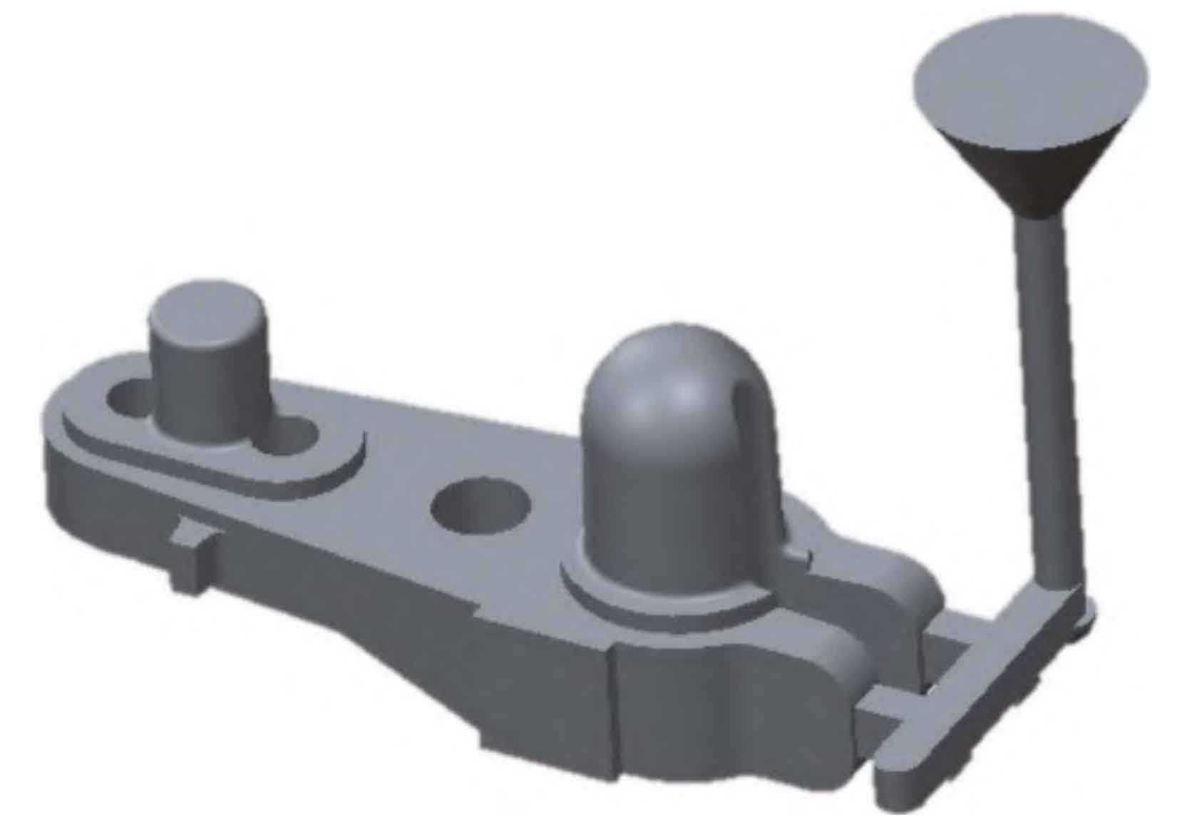
The inner runner is introduced from the length direction of the crank of the pumping unit to the two relatively weak flange vertical gates on the side near the keyway hole. The sectional area distribution ratio of each runner is ∑ S straight: ∑ S horizontal: ∑ S inner=1 ∶ 2.17 ∶ 2.51. Two risers are set on the highest plane respectively. In order to facilitate the simulation of sand casting process and view the results more accurately, sand mold risers are selected for each riser. Considering that the plane riser on the keyway hole near the runner is easy to shape and clean, a ϕ 200 mm × 250mm U-shaped random riser. At two places far away from the sprue ϕ Set one on the upper plane between 90 mm machining holes ϕ 118 mm × 130 mm riser. The process yield of single piece production is 68%, and the specific pouring and feeding system of Scheme A is shown in Figure 1.
(2) Scenario B
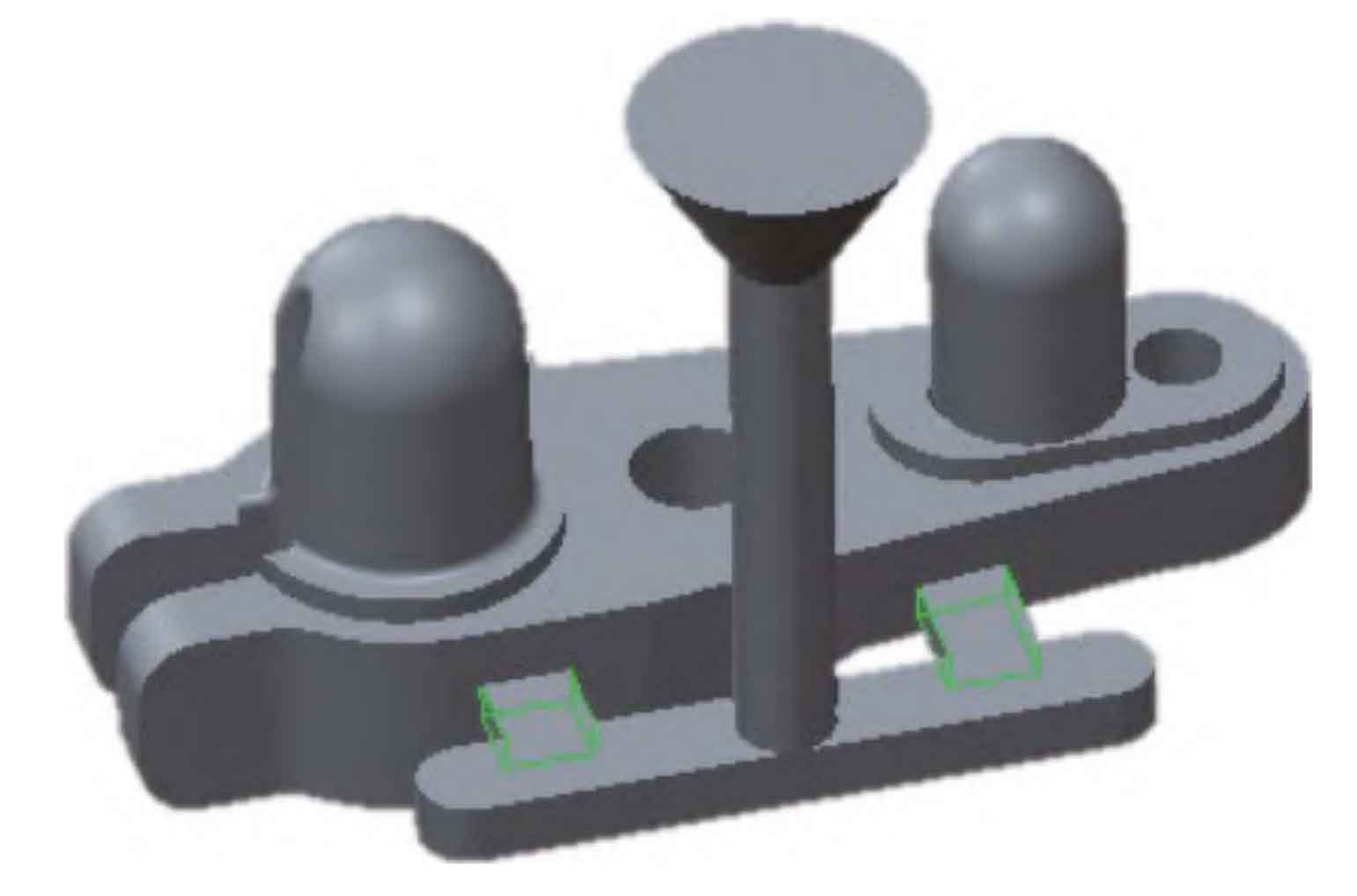
The sprue is introduced under the two risers on the side in the direction of the crank width of the pumping unit. In order to prevent the increase of the hot spot at the thick wall from being too large, the section shape of the inner gate is wide and flat. The sectional area distribution ratio of each runner is ∑ S straight: ∑ S horizontal: ∑ S inner=1 ∶ 1.95 ∶ 2.37. Two risers are set on the highest plane. In order to facilitate the simulation of sand casting process and compare the results of Scheme A and Scheme B more accurately, the sand riser is also selected. Set a key slot hole on the upper plane, which is the same as Scheme A ϕ 200 mm × 250mm U-shaped random riser. Consider two options B ϕ The upper plane between 90 mm machined holes is close to the runner, and one ϕ one hundred and fifty × 220. The process yield of single piece production is 62%, and the specific pouring and feeding system of Scheme B is shown in Figure 2.
(3) Numerical simulation of filling process
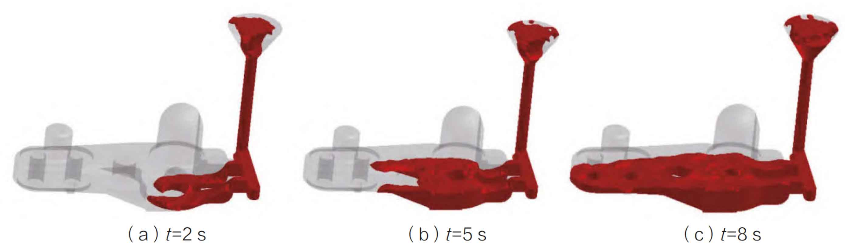
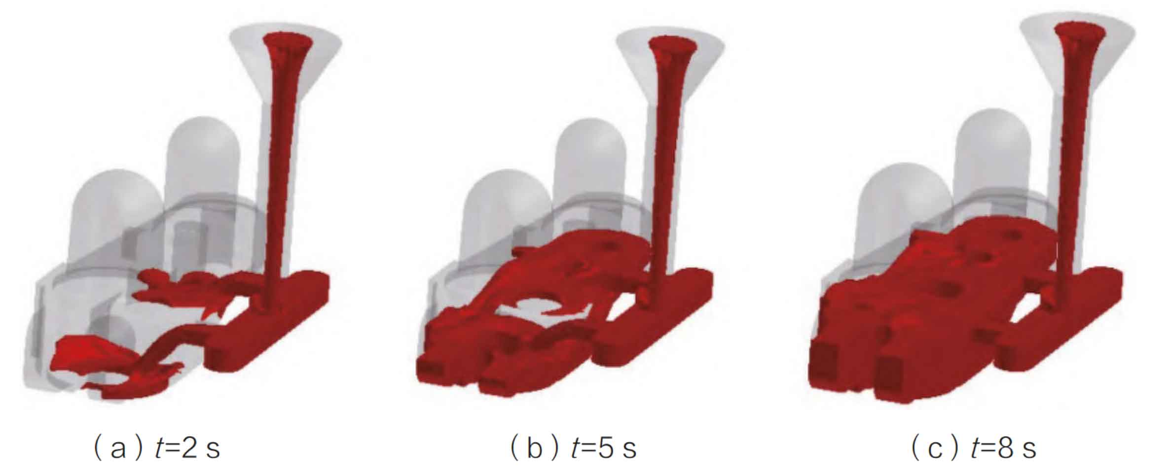
The 3D models of the two pouring schemes of the pumping unit crank sand casting are imported into the ProCAST software, and the numerical simulation of the sand casting filling process is carried out after the initial conditions and boundary conditions are set. The flow state of the molten steel entering the mold cavity is observed through the flow field simulation of the software, as shown in Figure 3 and Figure 4.
(4) Numerical simulation of solidification process
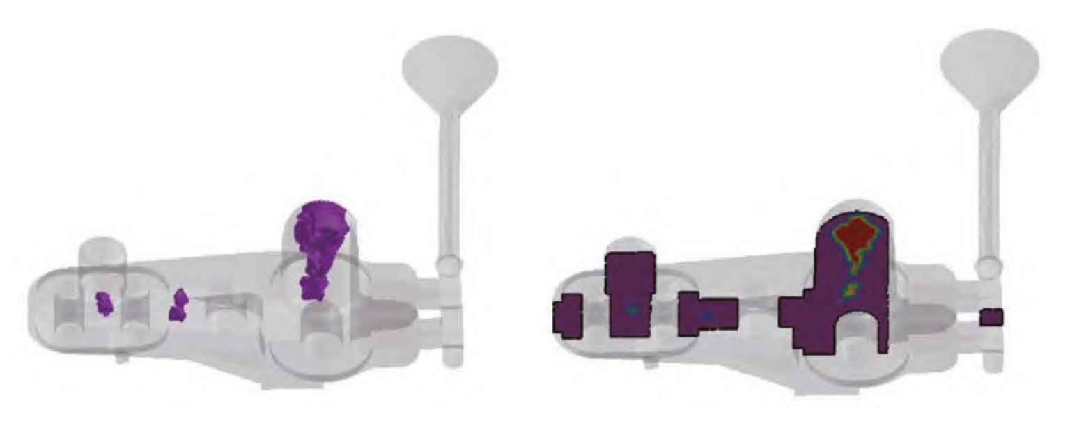
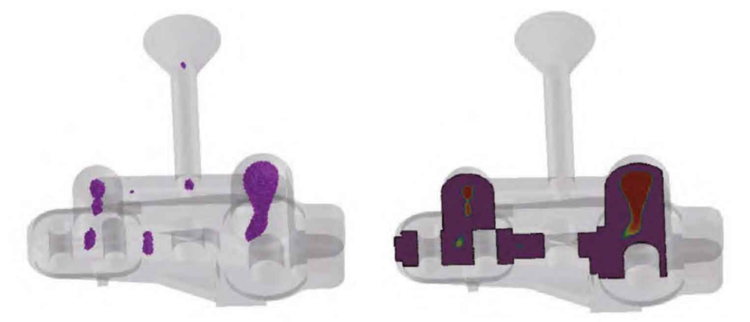
Carry out numerical simulation of the solidification process of the pumping unit crank sand mold casting with two pouring schemes, and then observe the location and size of shrinkage cavity and shrinkage porosity according to the porosity prediction function of sand mold casting of the software. See Fig. 5 and Fig. 6 for simulation results.
(5) Analysis of simulation results
From the flow of molten steel into the mold cavity, the molten steel in Scheme A flows rapidly and stably, and is easy to discharge gas. At the initial stage of liquid steel flowing into the cavity in Scheme B, the liquid steel is in a turbulent state, which is easy to get involved in gas and scour the cavity. Compared with the two schemes, the sprue of Scheme A is introduced along with the shape, and the lower part of the sprue is close to the bottom of the cavity, so the flow is more stable.
It can be seen from the results of numerical simulation of shrinkage cavity and shrinkage porosity of sand mold casting solidification in Scheme A and Scheme B that both of them have shrinkage cavity and shrinkage porosity near the riser root, and at the inner side ϕ There is shrinkage porosity at the center of one side of the 90 mm processing hole. Although the process yield of Scheme A is 68% higher than that of Scheme B, the size of shrinkage porosity and shrinkage porosity in Scheme A is significantly smaller than that in Scheme B, which indicates that the introduction of liquid steel in Scheme A from the thin wall is conducive to reducing shrinkage porosity and shrinkage porosity sand mold casting defects, and can also improve the process yield of sand mold castings. In addition, the large contact surface of the sand casting with the wide and flat inner runner in Scheme B makes it difficult to clean the sand casting in the later stage, which is easy to affect the surface quality of the sand casting. Through comprehensive analysis, Scheme A is superior to Scheme B.
According to the simulation results, optimize the feeding system process of Scheme A:
① Set one on the upper plane of key slot hole ϕ 180 mm × 250 mm insulated riser, two ϕ Set a 12/15K (specification: ϕ 118 mm × 130 mm).
② Set 2 external chills (specification: 50 mm) at the bottom of the relief hole near the keyway hole boss × 40 mm × 25 mm)。
③ On the inner side ϕ The upper and lower planes between the 90 mm processing hole and the relief hole are placed with chromite ore sand, with a thickness of not less than 20 mm.
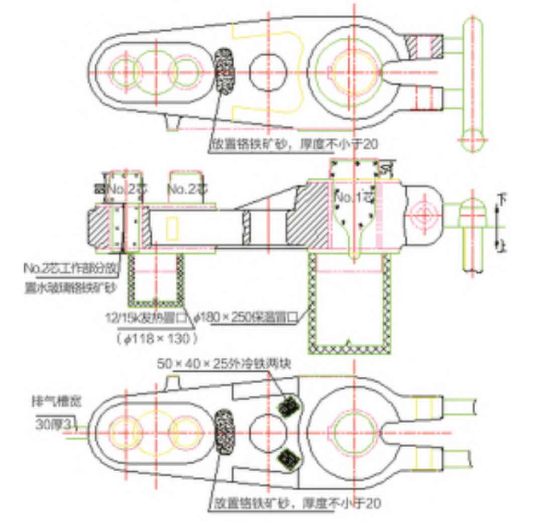
④ ϕ The working parts of two sand cores with 90 mm processing holes are made with sodium silicate chromite sand. According to these optimization measures of improving riser feeding efficiency and increasing riser feeding gradient, the sand mold casting process diagram (Fig. 7) was drawn. The process review team considered that the process was feasible.