
Process design parameters are some parameters related to the pattern and core box manufacturing size, which have a direct impact on the final casting dimensional accuracy. The important process design parameters of intake cylinder are: casting shrinkage, parting / core negative number, machining allowance, mold lifting angle, etc. most of the parameters can be selected according to casting process design manual, relevant domestic standards and casting technical conditions. Inaccurate selection of process design parameters will lead to large deviation of casting size and weight, and even lead to the size exceeding the tolerance requirements and scrapping.
(1) Casting shrinkage.
Casting shrinkage is a parameter to express the shrinkage of castings during solidification, which is affected by alloy types, cooling conditions and resistance during shrinkage. The shrinkage rate k can be expressed as:
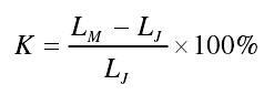
Where
LM – mold size (mold size);
LJ — final dimension of casting.
In addition to the investigation of alloy types and cooling conditions, the degree of shrinkage caused by sand mold resistance, the variation of wall thickness and thickness, and the difference of mold compactness should be comprehensively considered. Referring to the reference value of ferrite nodular cast iron in “casting shrinkage rate of general alloy castings in sand casting”, the casting shrinkage rate is 0.83%.
(2) Parting / core negative.
According to the technical requirements of actual operation, the parting surface must be trimmed during mold repair. When the mold is closed, the two sides of the mold surface are not tightly jointed, and the measures to prevent fire escape and mold crushing are taken, which will increase the casting size at the parting surface. Therefore, the corresponding size should be subtracted in the mold design to offset the increase in the final casting size The influence of size, this corresponding size is called the negative number of parting.
For the large and long cores manufactured by sections, the separation gap should be left at the joint of the core head. When the core is closed, the two sides of the core surface are not tightly connected, and the measures of anti drilling core and anti sand core crushing are taken, which will increase the overall size of the sand core on the parting surface The influence of inch on the final size of the casting is called the negative number of core separation by pre subtracting the corresponding size from the core box.
The selection of the negative number of parting / core is related to the size and structure of the casting, dimensional accuracy, mold accuracy and the operating habits of the foundry manufacturer. Our company generally selects the parting surface from 0 to 5 mm, selects the parting surface 2 and the upper parting surface with the parting negative number of – 2 / – 2mm and – 2mm, and the middle 1 and lower parting surface of the parting surface are sand filling mating surface, and no negative parting number is left.
(3) Machining allowance.
Machining allowance refers to the allowance pre added on the machining surface of casting and removed in subsequent machining. By increasing the machining allowance, the precision of casting surface can be ensured. The main reference factors for selecting machining allowance are: tolerance requirements of inlet cylinder casting, casting characteristics of nodular cast iron, casting and processing operation methods, equipment and process equipment, etc. When selecting the machining allowance of the inlet cylinder, a layer of liquid iron slag and other floating accumulation layer on the upper surface of the pouring position should be increased to 50 mm, and the other positions should be selected RMA (k) according to the size tolerance of ct11.
(4) Die lift angle.
In order to facilitate the mold lifting during the molding process, the slope set on the pattern and core box along the mold exit direction is used to ensure smooth demoulding and prevent damage to the sand mold and sand core. The main reference factors for the selection of the mold lift angle are: the unique structure of the complicated and gradual change of the inlet cylinder casting, the type of the mold, the surface finish of the mold, and the molding characteristics of resin sand. There are three kinds of die lift angles, as shown in the figure below. The red area in the figure represents the mold lift angle. The following principles shall be followed in the selection: the machining surface of the casting can be removed by machining and cutting, and the final wall thickness of the part will not be increased, so the method of increasing and decreasing the dimension (as shown in Fig. b) is generally adopted for the non machined surface which is not matched with other parts and has no special requirements for the wall thickness of the casting In order to prevent the assembly interference due to the excess thickness of the casting, the method of reducing the casting size is generally adopted (Fig. C).
Some parts designers have specified the requirements of mold lifting angle in the casting drawing design, so the casting process should not exceed the required value. The mold lift angle added to the casting shall not exceed the wall thickness tolerance of the casting. Fully understand the assembly requirements after casting is processed into parts, and the set mold lifting angle should not interfere with subsequent assembly.
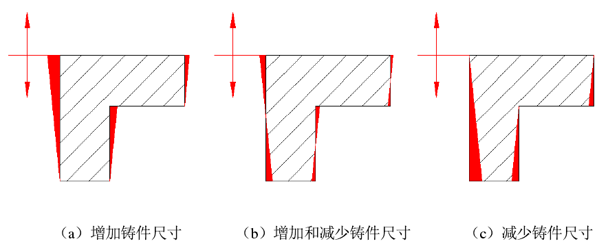
As shown in Fig. B, the feeding cylinder can select the way of increasing and decreasing the dimension to set the die lifting angle.