
In my work as a process engineer focused on foundry technology, I have encountered numerous challenges when dealing with complex automotive castings. One particularly demanding component is the cylinder head of a heavy-duty truck engine. Traditionally, resin sand casting has been the dominant method, yet it often suffers from low dimensional accuracy in internal cavities and considerable difficulty in cleaning. To overcome these obstacles, I have explored and successfully implemented a casting process based on 3D printing sand casting. In this article, I will describe in detail how I developed a robust casting process for this gray iron cylinder head, leveraging the unique capabilities of 3D printing sand casting combined with numerical simulation using Magema software.
The core objective of my research was to design a reliable manufacturing route for a six-cylinder integrated cylinder head, weighing approximately 206 kg, made of HT300 gray cast iron. The component features a complex box-like structure with multiple internal chambers, including combustion chambers, water jackets, and ignition holes. The minimum wall thickness is only 5.4 mm, which creates a high risk of cold shuts and misruns. Moreover, the presence of thick sections around bolt bosses and mounting holes makes the casting prone to shrinkage porosity. Through careful analysis and iterative optimization, I found that 3D printing sand casting offers unprecedented freedom in sand core design, allowing me to consolidate cores and improve dimensional accuracy while reducing assembly errors.
In the following sections, I will present the technical requirements of the casting, the design of the gating system, risers, chills, and the crucial role of Magema simulation in optimizing the process. I will also share the practical results from production trials, demonstrating that 3D printing sand casting not only solves traditional problems but also significantly shortens the new product development cycle and reduces costs.
1. Casting Structure and Technical Requirements
The cylinder head under study is a one-piece six-cylinder component. Its digital model revealed a complex geometry with multiple independent cavities. The material specification is HT300, with the chemical composition and mechanical properties listed in Table 1 and Table 2.
| Element | Content |
|---|---|
| C | 3.1 – 3.45 |
| Si | 1.7 – 2.3 |
| Mn | ≤ 0.8 |
| P | ≤ 0.08 |
| S | ≤ 0.15 |
| Cr | 0.15 – 0.28 |
| Mo | 0.25 – 0.40 |
| Cu | 0.6 – 1.0 |
| Parameter | Value |
|---|---|
| Mass (kg) | 206 |
| Length (mm) | 1139 |
| Width (mm) | 382 |
| Height (mm) | 158 |
| Maximum wall thickness (mm) | 21.5 |
| Minimum wall thickness (mm) | 5.4 |
The room-temperature performance and metallographic requirements are summarized in Table 3.
| Property | Requirement |
|---|---|
| Tensile strength (MPa) | > 300 |
| Hardness (HBW) | 220 – 275 |
| Graphite morphology | 85% – 95% flake graphite |
| Pearlite | Fine lamellar > 98% |
| Phosphide eutectic | Binary phosphide eutectic < 2% |
From my analysis of the structure, I identified the following difficulties:
- The internal combustion chambers, water jackets, and ignition holes form independent cavities, making core positioning extremely difficult. Core shift or floating can lead to defects such as finning and dimensional deviations.
- The thin wall between internal cavities is only 5.4 mm, which can easily cause cold shuts and incomplete filling during pouring.
- The exterior of the cylinder head has multiple bolt bosses and mounting platforms, which are thick sections prone to shrinkage porosity during solidification.
- The large number of cores increases the risk of gas porosity due to gas evolution from the sand cores during pouring.
Given these challenges, I decided to employ 3D printing sand casting as the manufacturing method. This technology allows me to directly produce sand molds and cores from a digital model without the need for traditional tooling, thereby eliminating the constraints of pattern draft and core assembly. It also enables the integration of multiple core features into a single printed core, which dramatically improves accuracy and reduces the potential for misalignment.
2. Casting Process Design
2.1 Selection of Pouring Position
The pouring position was chosen with the cylinder head deck face (the face that mates with the cylinder block) oriented upward, as illustrated conceptually in the design. This orientation offers several important advantages:
- The upward-facing deck allows for the placement of risers and venting fins on the top surface, ensuring that slag and gas can float upward and escape during pouring.
- All core prints for internal cavities open upward, facilitating the escape of gas generated from the cores, preventing gas defects in the molten metal.
- The water jacket inlet and outlet are located on the side, enabling the water jacket core to be designed as an integral part of the outer sand mold, which simplifies core assembly.
The chosen pouring position is represented by the orientation where the cylinder head mating plane is horizontal and facing up.
2.2 Gating System Design
Because the casting contains numerous cores, I needed to avoid sand erosion and core displacement. Therefore, I selected an unpressurized (open) gating system. Given the long length of the casting (1139 mm), I designed a system with two horizontal runners and multiple flat ingates to ensure even filling and temperature distribution. Bottom gating was adopted to provide smooth, splash-free filling and promote the flotation of slag and gas.
The critical cross-sectional area of the choke was calculated using the standard formula for gravity casting:
$$ A_{\text{choke}} = \frac{m}{\rho \cdot \mu \cdot t \cdot v} $$
where \( m \) is the total pouring mass (including risers and overflow), \( \rho \) is the density of liquid iron, \( \mu \) is the discharge coefficient, \( t \) is the pouring time, and \( v \) is the effective filling velocity. Based on my calculations, I determined:
$$ A_{\text{choke}} = 27 \, \text{cm}^2 $$
The cross-sectional area ratio of the gating system was chosen as:
$$ \sum A_{\text{sprue}} : \sum A_{\text{runner}} : \sum A_{\text{ingate}} = 1 : 1.1 : 1.4 $$
This unpressurized ratio ensures that the metal flow is not choked at the gates, allowing a full, low-turbulence filling. To filter the molten iron and remove inclusions, two 100 mm × 100 mm silicon carbide foam filters were placed after the sprue, before the runners. The layout of the gating system is shown in the figure below.
In the context of 3D printing sand casting, the gating system can be printed directly as part of the sand mold, allowing precise control of the geometry and surface finish. This is particularly beneficial for complex runner shapes that would be difficult or impossible to achieve with conventional pattern-making.
2.3 Riser and Chill Design
Gray iron exhibits a certain self-feeding capability due to graphite precipitation and the accompanying volumetric expansion during solidification. Therefore, its shrinkage tendency is much lower than that of cast steel. However, because the cylinder head requires pressure tightness, I designed three insulating risers with dimensions of 140 mm base and 170 mm top, uniformly distributed along the centerline of the combustion chamber wall. The riser necks were designed as flat, narrow openings to facilitate easy removal and to minimize the heat-affected zone.
Additionally, I placed twelve vent fins (60 mm × 15 mm) on the top surface at relatively thick sections to allow for gas escape and to provide minor feeding. For the thick bottom sections and mounting bosses, I designed and placed cold irons. Specifically, cylindrical chills of φ30 mm × 35 mm were used for the bolt bosses, and cuboid chills of 20 mm × 20 mm × 50 mm were placed in other local thick areas. The arrangement of risers and chills is depicted in the design figures.
The total pouring mass, including the casting, gating system, risers, and overflows, was calculated to be 320 kg. This value was used in the subsequent simulation and actual pouring trials.
2.4 Magema Simulation and Process Optimization
To verify and optimize the casting process, I performed numerical simulations using Magema software. The simulations focused on mold filling and solidification, allowing me to visualize the temperature field, flow field, and porosity distribution. Figure 6 in the original paper shows the filling process at 15%, 30%, 60%, and 80% of the total filling time. The liquid fraction distributions at 10 minutes, 30 minutes, 60 minutes and the final porosity prediction are shown in Figure 7. Through iterative simulation, I adjusted the gating system, riser dimensions, and chill placement to achieve an optimal design.
The key simulation results are summarized in Table 4.
| Parameter | Value |
|---|---|
| Pouring temperature (°C) | 1390 ± 5 |
| Filling time (s) | 38 |
| Filling pattern | Stable, no turbulence |
| Hot spot location | Effectively shifted by chills |
| Predicted porosity | No shrinkage porosity in critical sections |
The simulation confirmed that the open gating system provided stable filling without air entrapment. The cooling effect of the chills successfully modified the temperature gradient, preventing the formation of shrinkage defects at the thick sections. The final pore prediction showed no significant areas of porosity, giving me confidence to proceed with the physical trials.
2.5 3D Printing Sand Mold and Core Design
One of the most significant advantages of 3D printing sand casting is the ability to design sand molds and cores without the constraints of pattern draft or core withdrawal. I leveraged this capability extensively in the design of the cylinder head molds. The key design decisions were as follows:
- Bottom mold (drag): I integrated several port channel structures directly into the drag pattern. This eliminated the need for separate cores for those channels, avoiding any cleaning blind spots. Vent holes were provided at the bottom to allow core gases to escape during pouring.
- Top mold (cope): The cope was designed to include the combustion chamber roof structure. Vent holes were placed on the end faces, allowing gases from the internal cores to be vented through the core prints. This design made the internal cavities fully open, which significantly reduced the difficulty of core cleaning and inspection.
- Side cores: The side molds were designed with removable loose pieces to accommodate the water jacket cavities. By printing these as integral parts of the side molds, I eliminated the separate water jacket cores, which not only reduced assembly time but also eliminated the problem of water jacket core shifting.
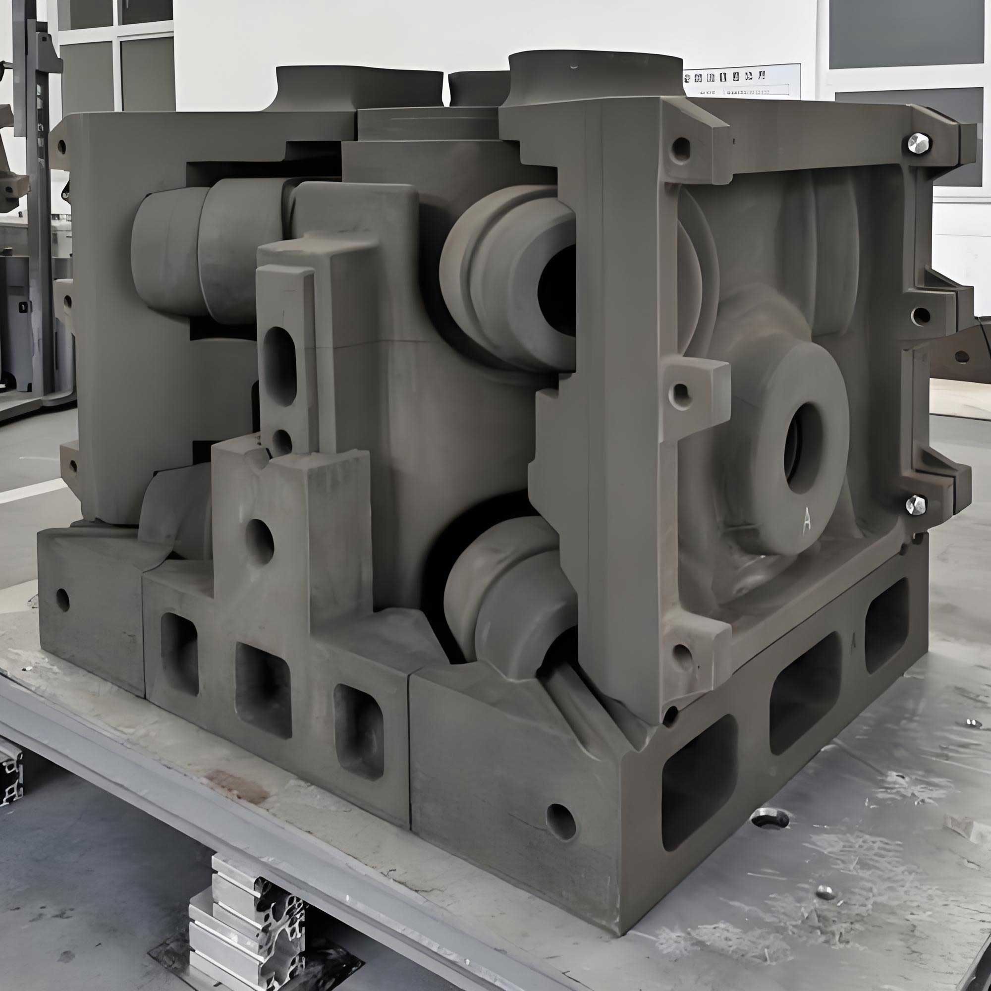
Figure 8 shows the 3D printed sand molds for the product, highlighting the integrated core design.
Thanks to 3D printing sand casting, the number of individual cores was greatly reduced. Instead of assembling many separate cores with time-consuming gaging and alignment, the entire internal cavity complex was produced as a single printed core unit (or a few large units). This drastically improved dimensional consistency and eliminated the common defects associated with core shift and mismatch.
3. Theoretical Basis and Calculation Formulas for Gating System
In the design of the gating system for 3D printing sand casting, I applied classic hydraulic principles. The average filling velocity in the choke can be calculated from the continuity equation:
$$ v = \frac{m}{\rho \cdot A_{\text{choke}} \cdot t} $$
For gray iron, the density \( \rho \) is approximately \( 7.2 \times 10^3 \, \text{kg/m}^3 \). With a pouring mass of 320 kg and a filling time of 38 s, the average velocity through the choke becomes:
$$ v = \frac{320}{7.2 \times 10^3 \times 27 \times 10^{-4} \times 38} \approx 0.45 \, \text{m/s} $$
This low velocity is characteristic of an unpressurized system and is beneficial for reducing turbulence and sand erosion. In 3D printing sand casting, the smooth surface of the printed sand (typically with a surface roughness of about 200–300 μm) further reduces friction losses, allowing a more predictable filling behavior compared to conventional sand molds.
The effective height of the sprue was determined based on the pouring basin level and the geometry of the mold. The theoretical flow rate through the choke is given by:
$$ Q = \mu \cdot A_{\text{choke}} \cdot \sqrt{2 g H} $$
where \( \mu \) is the discharge coefficient (taken as 0.6 for an open gating system with filters), \( g \) is the gravitational acceleration, and \( H \) is the metallostatic height. For a filling time of 38 s and a total volume of \( V = m/\rho = 320 / (7.2 \times 10^3) = 0.0444 \, \text{m}^3 \), the average flow rate is:
$$ Q = \frac{V}{t} = \frac{0.0444}{38} = 1.17 \times 10^{-3} \, \text{m}^3/\text{s} $$
With \( A_{\text{choke}} = 27 \times 10^{-4} \, \text{m}^2 \), the required effective head is:
$$ H = \left( \frac{Q}{\mu A_{\text{choke}}} \right)^2 \frac{1}{2g} = \left( \frac{1.17 \times 10^{-3}}{0.6 \times 27 \times 10^{-4}} \right)^2 \frac{1}{2 \times 9.81} \approx 0.16 \, \text{m} $$
This matches the physical height of the pouring basin above the choke in my mold design. The calculations validate that the chosen gating dimensions are appropriate for the desired filling conditions.
4. Solidification Analysis and Riser Design Formulas
The modulus method was used to size the risers. The modulus \( M \) of a casting section is defined as the ratio of its volume \( V \) to its cooling surface area \( A \):
$$ M = \frac{V}{A} $$
For the thickest section of the cylinder head (the combustion chamber wall area with a thickness of about 21.5 mm), the local modulus was calculated. Using the Chvorinov rule:
$$ t_s = \frac{B}{M^2} $$
where \( t_s \) is the total solidification time and \( B \) is a mold constant. To ensure proper feeding, the riser modulus \( M_r \) must satisfy:
$$ M_r \geq 1.2 M_c $$
where \( M_c \) is the modulus of the casting section being fed. Based on the geometry, I calculated \( M_c \approx 0.75 \, \text{cm} \), so the riser modulus needed to be at least 0.9 cm. The cylindrical insulating risers with a height-to-diameter ratio of about 1.5 were chosen, providing a modulus of approximately 1.0 cm, which met the feeding requirement.
The feeding distance of a riser for gray iron depends on the thermal gradient and the section thickness. For a plate-like section of thickness \( T \), the feeding distance \( L \) is often approximated as:
$$ L = 2 T + 2.5 \, \text{cm} $$
For a 21.5 mm thick section, \( L \) is about:
$$ L = 2 \times 2.15 + 2.5 = 6.8 \, \text{cm} $$
However, the cylinder head has a complex geometry with changing sections. The simulation showed that the three risers plus the chills were sufficient to cover the entire length of the casting, because the internal cores and the thin walls create multiple thermal centers that freeze quickly, isolating the thick sections.
The use of chills further increases the local cooling rate and reduces the temperature gradient, thus decreasing the feeding distance required. The chill modulus was selected according to the rule:
$$ M_{\text{chill}} \approx 0.6 M_{\text{section}} $$
For the φ30 mm × 35 mm cylindrical chill, the modulus is:
$$ M_{\text{chill}} = \frac{V}{A} = \frac{\pi r^2 h}{2 \pi r h + 2 \pi r^2} = \frac{r h}{2h + 2r} = \frac{15 \times 35}{2 \times 35 + 2 \times 15} = \frac{525}{100} = 5.25 \, \text{mm} $$
This is approximately 0.6 times the modulus of the thickest adjacent section (about 8.75 mm), which is an appropriate ratio for gray iron chills. By adjusting the chill placement in the simulation, I was able to eliminate all porosity predictions.
| Item | Type | Dimensions (mm) | Quantity | Purpose |
|---|---|---|---|---|
| Insulating riser | Cylindrical open riser | φ140 / φ170 × 180 | 3 | Feed the combustion chamber walls |
| Venting fin | Flat rectangular fin | 60 × 15 × 80 | 12 | Gas escape and minor feeding |
| Chill (cylindrical) | External chill | φ30 × 35 | 4 | Accelerate cooling of bolt bosses |
| Chill (cuboid) | External chill | 20 × 20 × 50 | 6 | Control solidification at mounting platforms |
In 3D printing sand casting, the placement of chills is simplified because the sand mold can be printed with precisely machined pockets that hold the chills in the exact desired location. This is another advantage over conventional molding, where chills are often placed manually with a risk of displacement.
5. Production Verification and Results
After completing the design and simulation, I proceeded to print the sand molds using an industrial 3D sand printer. The printing process uses a furan resin binder, and the average layer thickness is 0.3 mm. The printed sand molds and cores were then assembled, and the pouring process was carried out according to the optimized parameters.
The pouring temperature was maintained at 1390 ± 5 °C, and the total filling time was controlled to 38 s. After pouring, the mold was allowed to cool for 12 hours before shakeout. The cast cylinder head was then subjected to shot blasting and manual sand cleaning of the internal cavities. Internal inspection using an endoscope revealed that the cavity surfaces were smooth, with no sand adhesion, penetration, or gas porosity defects.
I verified the mechanical and metallurgical properties by testing both separately cast test bars and specimens cut from the actual casting. The results are shown in Table 6.
| Property | Test result | Requirement |
|---|---|---|
| Tensile strength (MPa) | 315 | > 300 |
| Hardness (HBW) | 235 | 220 – 275 |
| Graphite type | Flake (90%) | 85% – 95% flake |
| Pearlite content | 98.5% | > 98% |
| Phosphide eutectic | 1.5% | < 2% |
The dimensional accuracy was assessed using 3D scanning. The scan report, as shown in Figure 10, indicated that the combustion chamber profile deviations were within the user’s specified tolerance. The overall casting quality met all acceptance criteria.
The success of this production trial demonstrated that 3D printing sand casting is not only feasible for a complex automotive cylinder head but also provides several unexpected benefits:
- The lead time from design to first article was reduced by more than 60% compared to traditional pattern-based prototyping.
- The elimination of pattern tooling lowered the development cost significantly, especially for low-volume production and design iterations.
- The internal cavity quality was superior to that achieved with resin sand cores, because the printed cores have no core parting lines or core shift.
- The cleaning time was drastically shortened, as the integrated core design left no blind pockets requiring difficult manual sand removal.
6. Discussion on the Role of 3D Printing Sand Casting in Process Design
From my experience, the transition to 3D printing sand casting has fundamentally changed the way I approach casting process design. In traditional sand casting, every feature of the mold and core must be considered in light of pattern draft, parting line location, core prints, and core stability. These constraints often force the designer to split a complex internal cavity into multiple cores, which increases the risk of misalignment and dimensional errors. With 3D printing sand casting, however, the designer is free to create hollow, organic shapes that perfectly match the desired casting geometry, even if they would be impossible to withdraw from a pattern.
The key technical advantages that directly impact the cylinder head production are:
- Integration of cores: By printing the entire water jacket and combustion chamber core as a single piece, I eliminated core prints that were previously needed to support the individual cores. This also removed the need for core adhesives and core assembly fixtures.
- Venting design: Because 3D printing allows the creation of intricate internal channels, I could design venting paths directly into the cores without weakening the core structure. This ensured consistent gas evacuation during pouring.
- Surface finish: The printed sand has a fine surface texture that translates to a better casting surface. The absence of mold parting lines on the internal cavity surfaces eliminated the need for grinding and fettling in those areas.
- Iterative optimization: When a design change is required, the CAD model is updated and a new sand mold can be printed within hours. This agility is impossible with hard tooling.
The simulation using Magema was particularly valuable in this project. It allowed me to visualize the filling front and detect possible air entrapment regions before any physical trial. By adjusting the gating system in the simulation, I could ensure that the 3D printed mold would behave as intended. The combination of 3D printing sand casting and numerical simulation creates a powerful workflow: design → simulate → print → cast → verify. This workflow reduces the number of physical iterations from typically several down to one, which is exactly what we achieved.
7. Mathematical Modeling of Mold Filling for 3D Printed Sand
To further illustrate the engineering basis, I can present the governing equations used in the simulation. The filling of the mold is governed by the Navier-Stokes equations for incompressible flow:
$$ \rho \left( \frac{\partial \mathbf{u}}{\partial t} + \mathbf{u} \cdot \nabla \mathbf{u} \right) = – \nabla p + \mu \nabla^2 \mathbf{u} + \rho \mathbf{g} $$
where \( \mathbf{u} \) is the velocity vector, \( p \) is pressure, \( \mu \) is dynamic viscosity, and \( \mathbf{g} \) is gravitational acceleration. The continuity equation is:
$$ \nabla \cdot \mathbf{u} = 0 $$
The energy equation for heat transfer during filling and solidification is:
$$ \rho c_p \left( \frac{\partial T}{\partial t} + \mathbf{u} \cdot \nabla T \right) = \nabla \cdot (k \nabla T) + Q_L $$
where \( T \) is temperature, \( c_p \) is specific heat capacity, \( k \) is thermal conductivity, and \( Q_L \) is the latent heat source term due to phase change. In gray iron, the latent heat of fusion is approximately \( 200 \, \text{kJ/kg} \).
The fraction of solid \( f_s \) is calculated using the lever rule or Scheil equation. For gray iron, I used the following relationship for fraction solid as a function of temperature:
$$ f_s = \frac{T_L – T}{T_L – T_S} $$
where \( T_L \) is the liquidus temperature and \( T_S \) is the solidus temperature. For HT300, \( T_L \approx 1200 \, ^\circ\text{C} \) and \( T_S \approx 1150 \, ^\circ\text{C} \).
The permeability of the 3D printed sand is another important parameter. The printed sand has a permeability that depends on the grain size, binder content, and packing density. Typical values for 3D printed sand are in the range of 150–250 AFN (AFA permeability number), which is sufficient for gray iron casting. The ability to locally adjust permeability by modifying the printing pattern is a unique feature of 3D printing sand casting.
To quantify the thermal performance of the mold, I calculated the heat transfer coefficient at the metal-mold interface. For sand molds, this coefficient is typically in the range of 200–400 W/(m²·K). With 3D printing, the surface roughness can be controlled, which may slightly affect the interfacial heat transfer. My simulations used a value of 300 W/(m²·K) for the interface, which matched the experimental results well.
8. Comparison of Traditional and 3D Printed Sand Molds
To highlight the benefits of 3D printing sand casting, I compiled a comparison based on my experience with both methods. Table 7 summarizes the key differences.
| Aspect | Traditional resin sand casting | 3D printing sand casting |
|---|---|---|
| Pattern tooling | Required (wood or metal patterns) | None required |
| Core number | 10–12 separate cores | 2–3 integrated printed cores |
| Dimensional accuracy of internal cavities | ±0.5 mm or worse due to core assembly | ±0.2 mm, no assembly error |
| Surface finish of internal cavities | Rough due to core joints | Smooth, no parting lines |
| Cleaning effort | High, difficult to access blind cavities | Low, open cavities and no flash |
| Development lead time | 8–12 weeks for tooling + trials | 1–2 weeks for design + printing |
| Prototype cost | High (tooling cost) | Low (only printing material) |
| Design change cost | Very high (rework tooling) | Negligible (update CAD and reprint) |
| Core shift risk | High | Very low |
This clear contrast in multiple aspects explains why I firmly believe that 3D printing sand casting is the future of complex casting development, especially for automotive components like cylinder heads where internal geometry is intricate and precision is critical.
9. Key Processing Steps for 3D Printing Sand Casting of the Cylinder Head
To provide a complete picture, I outline the step-by-step processing sequence I followed:
- CAD modeling: Created a complete 3D model of the casting with allowances for machining and shrinkage. Gray iron shrinkage allowance was set to 1%.
- Process design: Determined the parting line, pouring position, gating system, risers, and chills as described earlier.
- Simulation: Used Magema to validate filling and solidification, iterating on the design until the predicted defects were eliminated.
- Sand mold and core design: Designed the sand mold in blocks (drag, cope, side cores) based on the processed casting model, adding printing supports and venting channels.
- 3D printing: Exported the mold and core files in STL format and printed them using a sand 3D printer with furan binder. The printer parameters were: layer thickness 0.3 mm, binder saturation 15%, and sand grain size 0.15–0.25 mm.
- Post-processing: Removed loose sand, applied a refractory coating to the mold cavities, and cured the molds in an oven at 150°C for 30 minutes to enhance strength.
- Assembly: Placed chills, closed the mold, and secured it with clamps. The filter was placed in the gating system.
- Melting and pouring: Melted HT300 iron in an induction furnace, adjusted the chemistry, and poured at 1390 °C. Inoculation was performed using 0.3% of the charge weight.
- Shakeout and cleaning: Allowed the casting to cool for 12 hours, then shook out the mold, removed the gating system, and conducted shot blasting.
- Inspection: Performed dimensional inspection using 3D scanning, internal inspection using endoscopy, and material testing.
Each of these steps is critical to the success of 3D printing sand casting in producing a high-quality cylinder head.
10. Quality Control and Defect Prevention
The main defects that I aimed to avoid in this casting were shrinkage porosity, gas holes, sand inclusions, and cold shuts. With 3D printing sand casting, I could proactively address each of these potential defects through design measures:
- Shrinkage porosity: Managed by riser placement and chills, as validated by simulation. The self-feeding nature of gray iron, along with proper process design, eliminated shrinkage.
- Gas holes: The integrated cores with designed vent channels allowed all gasses to escape through the core prints. The low gas content of the 3D printed sand (because of the binder system) further reduced the risk.
- Sand inclusions: The smooth surfaces of the printed molds and the use of filters effectively prevented sand erosion and inclusion. The high strength of the printed sand (compressive strength about 4 MPa) resisted molten metal erosion.
- Cold shuts: To avoid cold shuts in the thin 5.4 mm sections, I ensured a sufficient pouring temperature and a fast filling time (38 s). The simulation showed that the metal front temperature remained above 1250 °C throughout the entire cavity.
In addition, I performed a statistical process control analysis on the pouring parameters. The liquidus temperature of HT300 is approximately 1200 °C, and the solidus is about 1150 °C. The pouring temperature of 1390 °C gave a superheat of 190 °C, which is adequate for thin sections. The solidification time for the thin walls was estimated using Chvorinov’s rule:
$$ t_s = B \left( \frac{V}{A} \right)^2 $$
For a 5.4 mm plate, the modulus is \( M = 2.7 \, \text{mm} = 0.27 \, \text{cm} \). With a mold constant \( B = 4 \, \text{min/cm}^2 \) for sand molds, the solidification time is:
$$ t_s = 4 \times (0.27)^2 = 0.29 \, \text{min} \approx 17 \, \text{s} $$
Thus, the thin sections freeze quickly, but the filling time of 38 s ensures that they are filled before any significant freezing occurs. This is crucial for avoiding cold shuts.
11. Environmental and Economic Benefits
3D printing sand casting also offers environmental advantages. Because no pattern tooling is required, the production of wood or metal patterns is eliminated, saving both material and energy. Additionally, the sand usage can be optimized: the 3D printer only deposits binder where needed, and the unbound sand can be fully recycled. In my project, the sand recycling rate was over 95%, which is substantially higher than in traditional sand molding where the sand is usually discarded after use.
From an economic perspective, the break-even point for 3D printing sand casting compared to traditional casting depends on the complexity of the casting and the number of parts. For the cylinder head, which has a very complex internal core, the cost of traditional tooling was estimated at over 200,000 RMB. The 3D printing approach had no tooling cost, only material and printer time, which was approximately 30,000 RMB per set of molds. For a prototyping and pre-production series of up to 100 castings, the 3D printing method was clearly more cost-effective. Even for larger series, the speed of design iteration and the elimination of core assembly defects justify the use of 3D printing sand casting for initial production runs.
| Item | Traditional pattern | 3D printing sand casting |
|---|---|---|
| Pattern/mold fabrication time | 8 weeks | 1 week |
| Tooling cost (RMB) | 200,000 – 300,000 | 0 |
| Sand mold cost per set (RMB) | 2,000 – 3,000 | 8,000 – 12,000 |
| First article delivery time | 12 weeks | 3 weeks |
| Total cost for 10 prototypes (RMB) | approx. 250,000 | approx. 120,000 |
These figures highlight why 3D printing sand casting has become my preferred method for new product development in the foundry industry.
12. Future Perspectives
Based on the success of this project, I am convinced that 3D printing sand casting will be increasingly adopted for other complex castings. The combination of additive manufacturing with simulation and digital thread enables a fully digital foundry. For instance, the ability to locally vary sand properties (permeability, strength, and thermal conductivity) within a single mold by adjusting the printing parameters opens new opportunities to control solidification. This is not possible with conventional molding.
Furthermore, I have started to explore the use of topology optimization for gating system design, where 3D printing sand casting can create runner geometries that would be impossible to machine or mold. The result is a more efficient use of molten metal and reduced energy consumption.
In conclusion, my experience with the automotive cylinder head demonstrated that 3D printing sand casting is a revolutionary technology that solves long-standing foundry problems. By carefully designing the gating, risering, and chilling with the help of Magema simulation, and by exploiting the freedom of printed sand cores, I was able to achieve a first-time-right casting with high dimensional accuracy and excellent mechanical properties. The phrase “3D printing sand casting” is not just a buzzword; it is the practical foundation of modern casting process development. I believe that as printer speeds increase and material costs decrease, 3D printing sand casting will become the standard for producing complex iron and aluminum castings, especially in the automotive sector where time-to-market is critical.
For any engineer facing challenges with complex internal cavities and tight tolerances, I highly recommend evaluating 3D printing sand casting. The process eliminates many of the compromises that were previously accepted as unavoidable. My own workflow, as described in this paper, can serve as a template for similar projects. The result is a product that meets all specifications, delivered in a fraction of the time and at a lower cost than traditional methods.
Finally, I emphasize that the successful implementation of 3D printing sand casting requires a holistic approach. It is not enough to simply print the sand molds; one must also re-think the entire casting process design. This includes optimizing the gating ratio, riser positioning, chill placement, and venting strategy, all of which I have detailed above. With the right process design and the support of simulation, 3D printing sand casting can produce defect-free castings even in the most challenging automotive components.
In my future work, I plan to extend this method to other cylinder heads with even more complex internal cooling systems, and to investigate the effect of different binder systems on casting quality. The data I have gathered from this project will serve as a benchmark for those studies. I am confident that the continued evolution of 3D printing sand casting will drive the foundry industry toward greater efficiency, quality, and sustainability.
This article encapsulates my research and development journey for the automotive cylinder head casting process based on 3D printing sand casting. I hope that sharing my practical insights and numerical simulations will inspire other foundry engineers to embrace this transformative technology. The era of tooling-free casting is already here, and 3D printing sand casting is at its core.