Different casting methods require different molds. The sand casting mold for turbine housing castings mainly consists of the molds required to prepare the sand molds and the core molds required to prepare the cores, which are convenient for the dummy boxes used for the irregular parting surface sand molds, as well as the metal cores and external chills required to control the solidification and concurrent forming.
1. Design of pattern
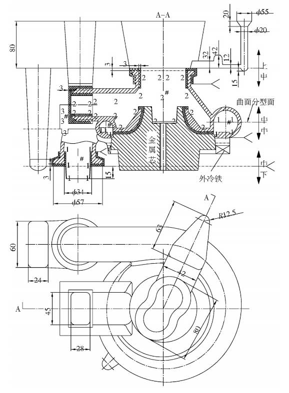
The pattern is the process equipment to simulate the shape of the castings to form the sand mold cavity. The design principle is as follows: each part must be able to withdraw from the sand mold along the parting surface. Therefore, the pattern must be partitioned from the local maximum section, positioned with locating pin and combined in several sections. As shown in Figure 1, the center of the middle straight pipe is above the spiral case parting line. Here, the sand core that divides the center of the straight pipe downwards along the spiral case parting line is used.Type A, which ensures maximum projection on the volute parting line and forms a cavity for placing sand core after parting the volute section.
2. Design of dummy boxes
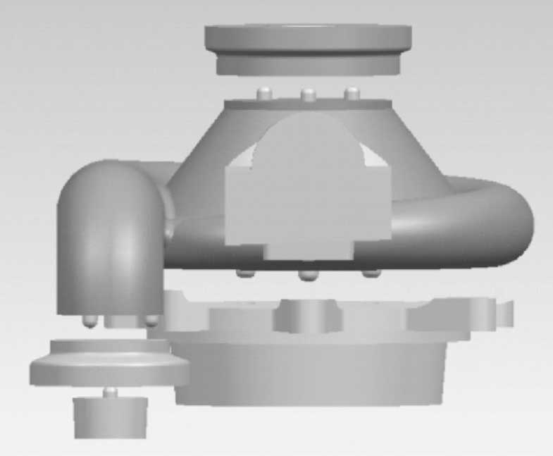
The maximum section is the horizontal pattern section. The pattern can be obtained by scraping flat along the horizontal parting surface in the sand mold. However, the parting surface height of the spiral case part of the casting changes from low to high and the surface height differs by 11mm. As shown in Figure 2, the spiral case part is first formed along the lower half of the parting surface by the combination of dummy box and pattern, and then combined with the turned sand model and pattern.Turn over the top half of the volute part of the castings to ensure that the volute part of the castings is classified along the maximum section with gradual change in height to form a curved surface without sand excavation and with a neat parting surface.
3. Design of Sand Core and Metal Core
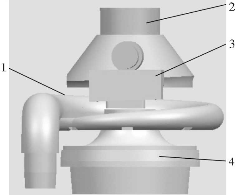
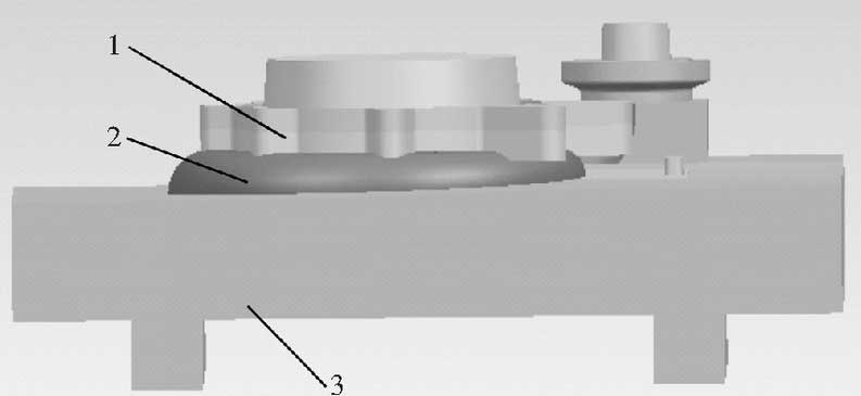
As shown in Figure 3, the internal shape of the turbine housing casting is formed by two sand cores and one metal core. The internal shape of the spiral case of the sand core I forming casting, the flare-shaped and straight pipe structure of the sand core II forming, the outer surface of the lower half of the center of the straight pipe formed by the sand core III forming, the flare-shaped structure of the inner metal core forming and the chilling effect of the outer chilled iron on the hot spot are related with each other to a certain position.It is necessary to consider positioning between cores. As shown in Figure 6, the positioning cores of each core are designed as special-shaped structures. Metal core and core I are positioned as special-shaped cores, while core II is positioned as grooves along the periphery with a small convex. The part of the core head of the metal core has special-shaped conical surfaces consistent with the shape of the pattern, and the three special-shaped positioning surfaces are in the same direction in 1, 2 and 3, which ensures the spiral shell bends the turbine housing casting.Relative position relationship between horizontal straight pipe and 8 lugs.The metal core is pulled out along one end of the core head, and through holes are made in the center and threads are tapped at both ends to facilitate the exhaust of the sand core II and the demoulding of the metal core after being put into the sand mold and the cast.
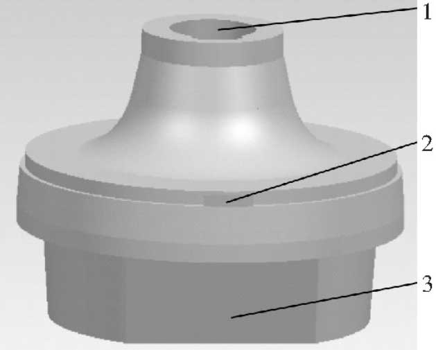
1. Locating Surface I 2. Locating Surface II 3. Locating Surface III
4. Design of outer cooling iron
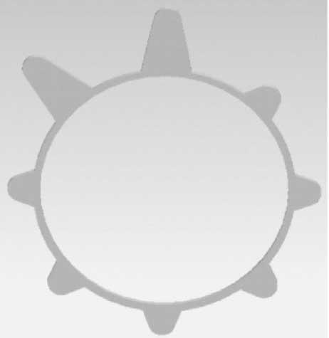
As shown in Figure 4, the outer cold iron has the same shape as the eight flanges of the casting. As shown in Figure 5, the outer cold iron is affixed to the lower end of the flanges of the pattern when the pattern and the dummy box are turned over. When the pattern is taken out, the outer cold iron is embedded in the sand mould and can not be removed. During the casting process, the outer cold iron is a steel material whose thermal storage coefficient is different from that of the surrounding sand mold. Through introducing the molding material at the convex with thicker cast wall, the outer cold iron can be removed.To control the solidification of castings and accelerate the cooling rate of local hot joints at 8 protrusions of castings, simultaneous solidification can be achieved and casting shrinkage defects can be prevented.