
1. Original design scheme of nodular cast iron parts for high-pressure cylinder end cover
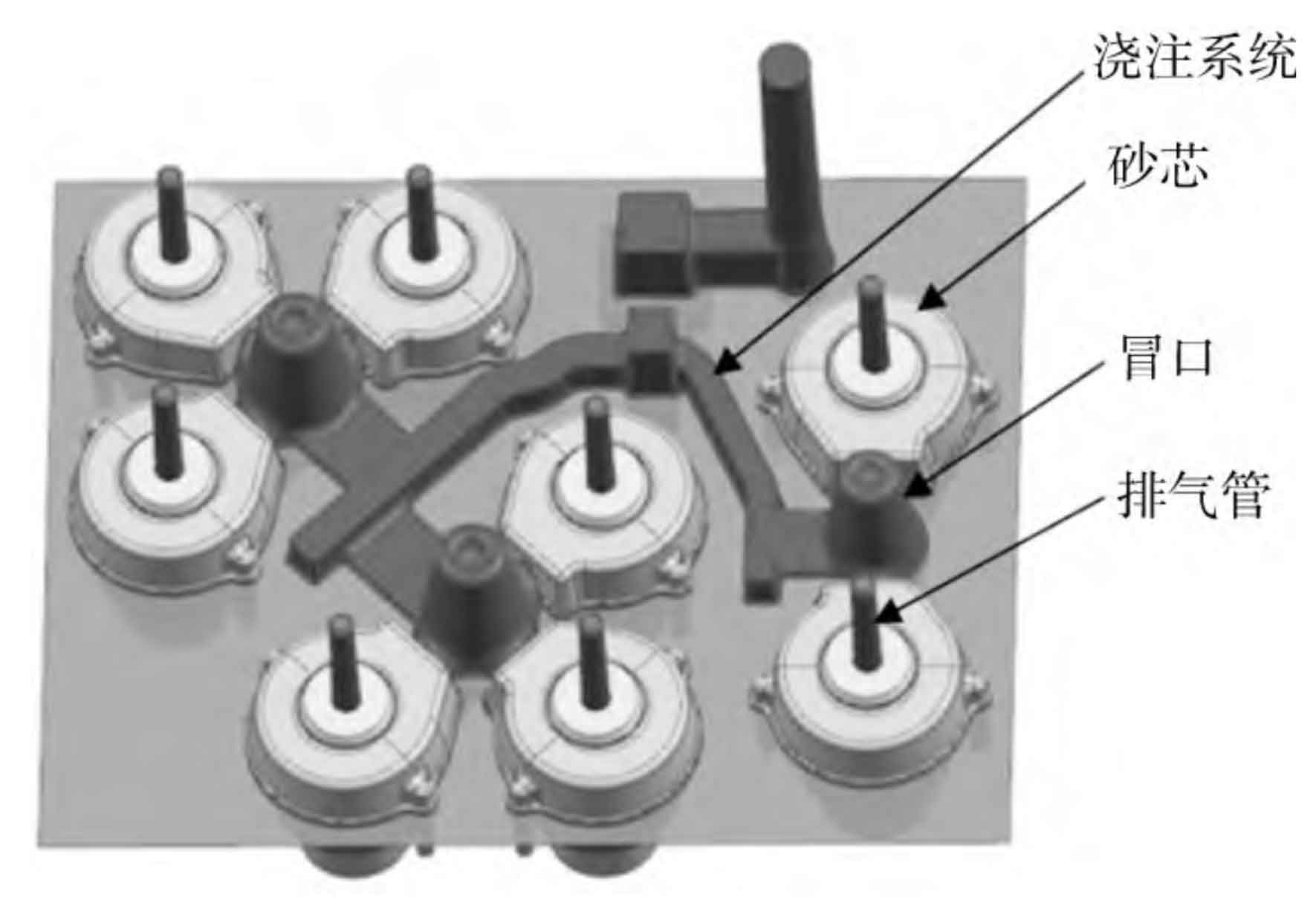
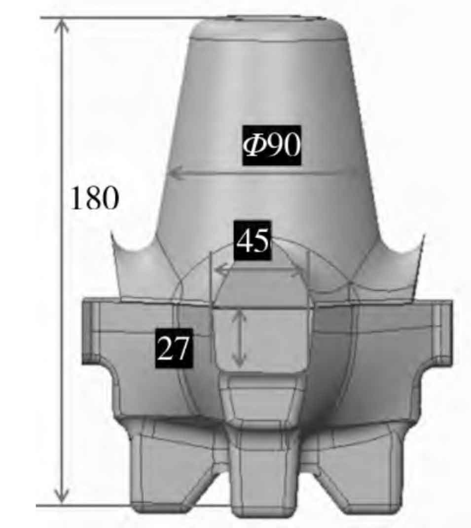
See Figure 1 for the original process diagram of nodular cast iron parts for the end cover of high-pressure oil cylinder. It can be seen from Figure 2 that the parts are arranged in 8 parts per module. Three risers are used for feeding (Fig. 2). Two risers are used for feeding three high pressure cylinder end cap ductile iron castings, and one exhaust pipe is placed on each ductile iron casting. The pouring system adopts the method of pouring molten iron into the riser. The weight of the whole pouring system is 138 kg, the pouring time is 14 seconds, the upper cavity of the casting and the upper hole of the flange are formed by the shell mold, and the size of the riser neck is 45 mm × 27 mm, process yield 11.2 × 8/138=64.9%。
2. Quality and analysis of nodular cast iron parts of high pressure cylinder end cover
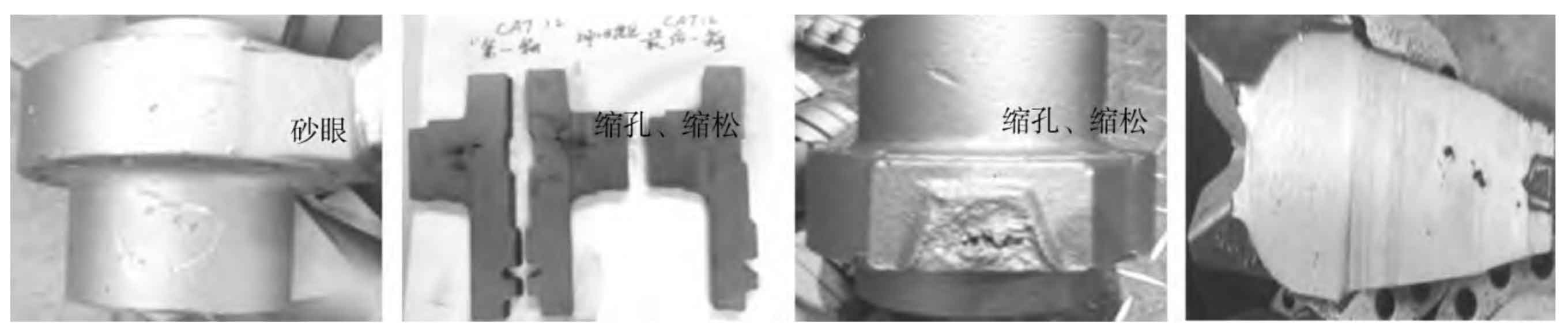
The spheroidal graphite cast iron parts of the high-pressure cylinder end cover produced by the original process plan produced sand holes, shrinkage porosity and shrinkage defects on the surface, which occurred at the fixed position of the riser neck, as shown in Fig. 3a, 3b and 3c, which seriously affected the quality of the parts, resulting in a product scrap rate of about 10%. Casting defects and low product qualification rate make the casting cost of high pressure cylinder end cap ductile iron castings significantly increased. After removing the riser of ductile iron castings (see Fig. 3d), it was found that there was shrinkage defect at the upper part of the riser, and there was no shrinkage defect at the middle and lower parts of the riser, which indicated that the size of the riser neck was too small to supplement the liquid shrinkage, and the cause of the defect might be due to the improper design of the size of the riser neck and its solidification time.
3. Simulation of the original design scheme of the nodular cast iron part of the high-pressure cylinder end cover
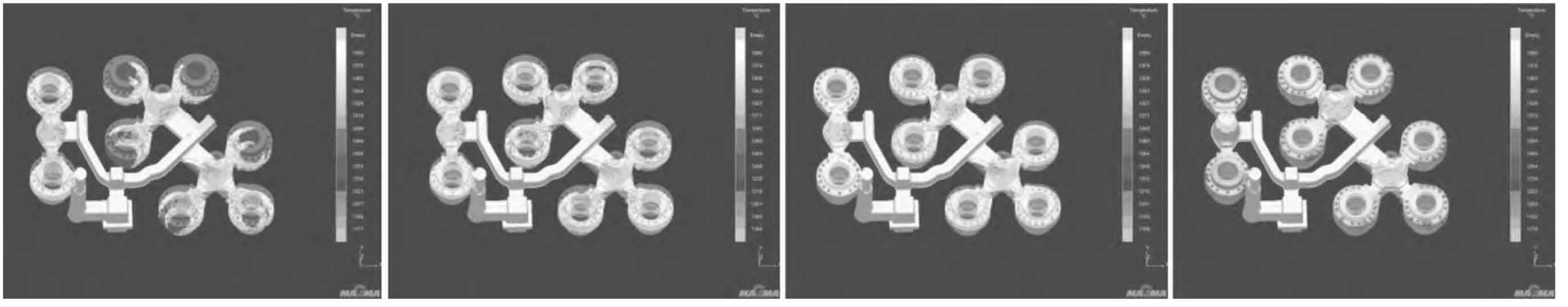
In order to further explore and confirm the causes of defects such as sand holes, shrinkage holes and porosity in the nodular cast iron parts of the high-pressure cylinder end cover, and provide visual analysis of the filling process. The MAGMA software is used to simulate the filling of each time period, and the results are shown in Figure 4. It can be seen that the mold filling is not stable during the pouring process. When the molten iron enters the common riser of the three ductile iron castings, there is a serious liquid level imbalance and turbulence, which may be the cause of sand holes.
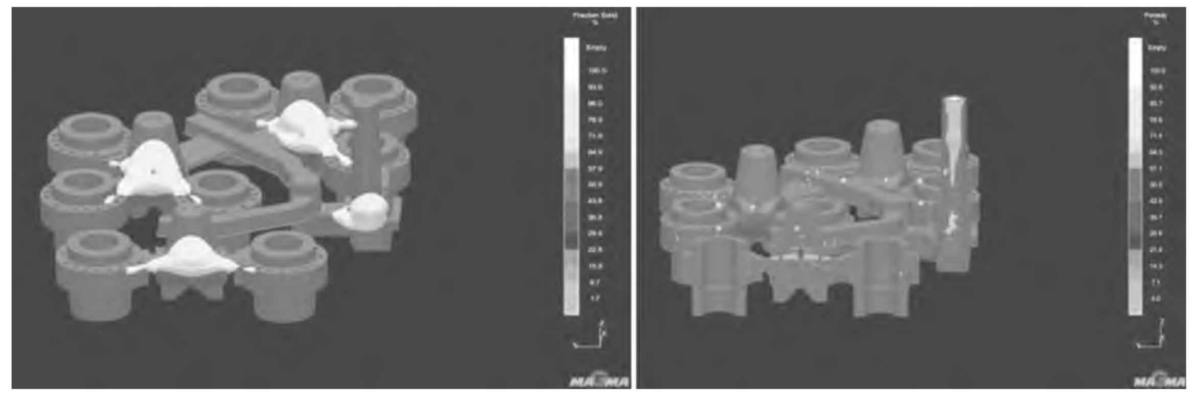
Figure 5 shows the simulation results of feeding system by MAGMA software. It can be seen from Fig. 5a that at the later stage of solidification, the ductile iron at the front end of the riser neck was prematurely disconnected from the riser, resulting in residual liquid phase, and the ductile iron could not be fed by molten iron. It can be seen from Figure 5b that the shrinkage porosity simulation shows that there are shrinkage cavities in the remaining liquid phase of ductile iron castings, and there may be casting defects. The original simulation results are supplemented to explain that the original simulation process is in a critical state. When the metallurgical quality of molten iron is good, the product has no shrinkage porosity problem; When the metallurgical quality is poor, shrinkage defects may occur, the process safety factor is not high, and the quality of molten iron fluctuates, resulting in a 10% scrap rate.