
I designed and evaluated a manufacturing route for crusher hammer heads in which a wear-resistant TiC steel-bonded cemented carbide column is embedded inside a ZGMn13 high-manganese steel matrix by combining inlay casting with lost foam casting. My goal was practical: increase service life, reduce premature replacement, and keep production cost under control. In my experiments, I treated the hammer head as a composite component rather than a single-material casting. The hard insert carried the abrasive load, while the high-manganese steel body provided toughness, shock absorption, and structural continuity. I used lost foam casting because it allows complex insert placement, reduces machining, produces good surface finish, and supports the production of composite parts with multiple materials. I used inlay casting because the latent heat of the poured metal can create a metallurgical bond between the insert and the matrix without requiring a separate joining operation.
I selected a TiC steel-bonded cemented carbide insert because it combines high hardness, wear resistance, and reasonable machinability. I selected ZGMn13 as the matrix because it can develop a tough austenitic structure after water toughening, and because its manganese content stabilizes the austenite phase. My central process question was whether lost foam casting plus inlay casting could produce a sound interface without pores, sand adhesion, or incomplete fusion. I also asked whether water toughening would preserve insert hardness while improving matrix toughness, and whether elemental diffusion of Mn, Ti, Fe, and C would be sufficient to create a reliable metallurgical bond.
In my work, the term lost foam casting refers to the expendable pattern process in which a foam pattern is coated, embedded in dry sand, and then vaporized by molten metal during pouring. The term inlay casting refers to the placement of a solid insert in the mold cavity so that the incoming liquid metal surrounds it, heats it, and bonds to it. When I combined lost foam casting with inlay casting, I obtained a route that was simpler than many conventional composite casting methods. The foam pattern held the insert in position, the refractory coating controlled surface quality, and the dry sand under vacuum supported the mold during vaporization. I repeated lost foam casting trials to confirm that the process could hold the insert without shifting, cracking, or causing surface defects.
I began with material selection because the success of inlay casting depends strongly on the compatibility between the insert and the matrix. The insert needed a thermal expansion coefficient close enough to that of ZGMn13 to avoid excessive interfacial stress. It also needed high hardness and wear resistance, and it needed to survive water toughening without cracking. I chose a GT35-type TiC steel-bonded cemented carbide column with a diameter of 12 mm and a length of 25 mm. I attached one end of the column to a small iron nail so that I could position and fix it inside the foam pattern. The nail acted as a temporary anchor, and I removed it after heat treatment by grinding.
| Material | Role in My Composite Hammer Head | Key Reason for Selection |
|---|---|---|
| ZGMn13 high-manganese steel | Main hammer body and tough matrix | High toughness, austenite stabilization by Mn, good impact resistance after water toughening |
| TiC steel-bonded cemented carbide | Wear-resistant embedded column | High hardness, good wear resistance, steel-like machinability, lower cost than tungsten carbide |
| Magnesia-based coating | Refractory coating for lost foam casting | Basic nature compatible with weakly alkaline high-manganese steel |
| Dry silica sand | Vacuum-supported molding medium | Good flowability, reusability, and dimensional support in lost foam casting |
| EPS foam pattern | Expendable pattern for lost foam casting | Easy shaping, low cost, clean vaporization during pouring |
| Iron nail | Temporary insert anchor | Holds the insert in the foam pattern before pouring |
The composition of the insert strongly influenced both hardness and bonding. I used a TiC content of about 35 mass percent, with C, Cr, Mo, and Fe balancing the steel binder. The Cr and Mo additions improved hardenability and temper resistance, while the steel binder provided enough ductility to avoid brittle fracture during cooling. I summarized the nominal insert composition in the table below. I did not treat the insert as a simple hard particle; instead, I treated it as a composite in which the TiC particles provide wear resistance and the steel binder provides continuity.
| Component | Mass Fraction (%) | Function in the Insert |
|---|---|---|
| TiC | 35 | Hard phase for wear resistance |
| C | 0.5 | Carbide formation and matrix strengthening |
| Cr | 2.0 | Hardenability and corrosion resistance |
| Mo | 2.0 | Hardenability, temper resistance, carbide stability |
| Fe | Balance | Steel binder for toughness and bondability |
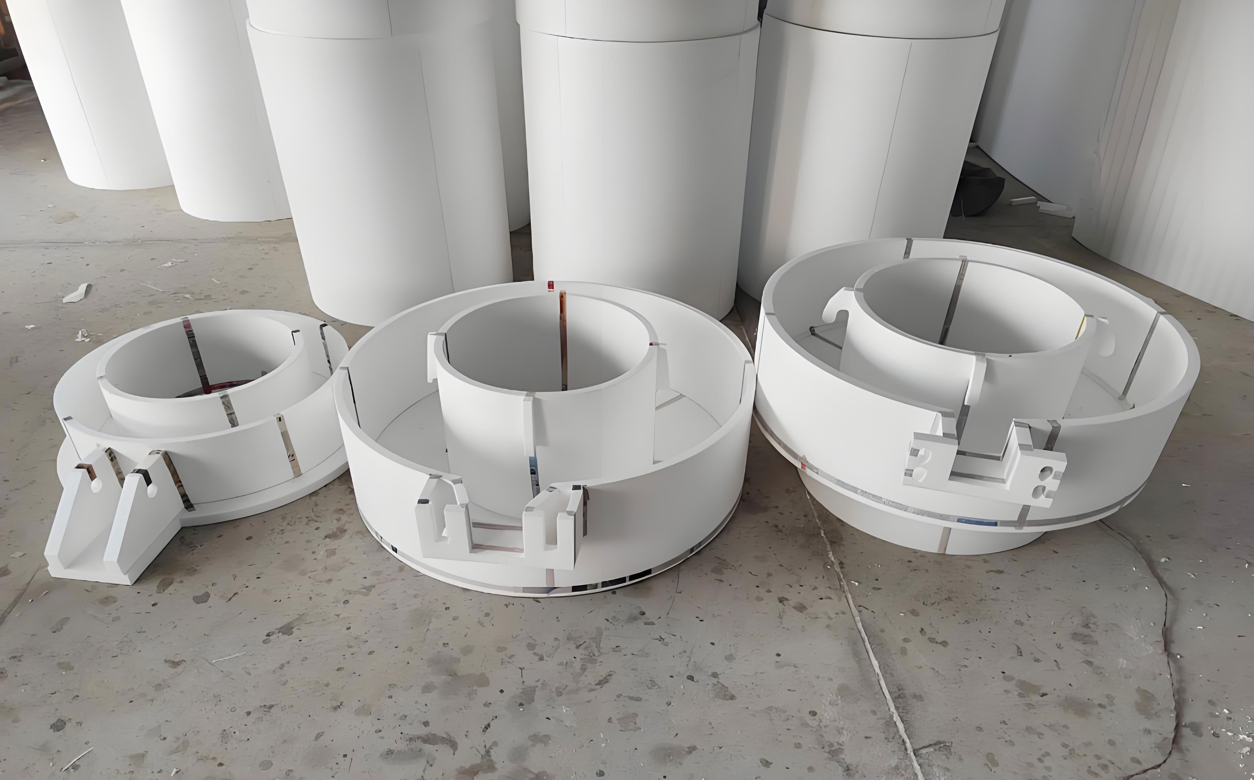
I prepared the foam pattern from EPS using a CAD-based outline. I cut the pattern with a foam cutting machine, then repaired any bead loss, torn surface, or wavy cavity. I dried the pattern to remove moisture before coating. For lost foam casting, pattern quality matters because the foam surface directly affects coating coverage, sand filling, and final casting surface finish. I inspected the pattern carefully before the first coating step. Any local depression or loose bead would have created a coating defect and later a surface defect on the hammer head.
I used a magnesia powder coating because ZGMn13 is weakly alkaline and magnesia is also basic. I did not want an acidic coating to react with the high-manganese steel. I applied the first coating by dipping and brushing, then dried the pattern for 24 hours. I applied a second coating and dried it for another 24 hours at 50 to 55 degrees Celsius. I repeated the coating procedure until the coating thickness reached 1.5 to 2.5 mm. I then repaired local areas and fixed the TiC steel-bonded cemented carbide column in the working face of the pattern. In my process, the coating served three functions: it protected the pattern, it controlled the mold surface, and it helped regulate heat transfer during pouring.
| Pattern and Coating Step | My Parameter or Practice | Reason |
|---|---|---|
| Pattern material | EPS foam | Clean vaporization and easy shaping in lost foam casting |
| Pattern preparation | CAD outline, foam cutting, repair, drying | Accurate dimensions and defect-free surface |
| Coating type | Magnesia powder | Basic coating compatible with ZGMn13 |
| First drying | 24 h | Remove water and develop green strength |
| Second drying | 24 h at 50-55 °C | Complete drying and improve coating integrity |
| Final coating thickness | 1.5-2.5 mm | Balance permeability, strength, and surface finish |
| Insert fixation | TiC column anchored in working face | Keep the insert in the correct position during pouring |
For molding, I placed a special sand box on a vibration table and added about 100 mm of dry silica sand as bottom sand. I used silica sand with a grain size of about 20 mesh. I vibrated the sand, leveled it, and then positioned the coated hammer pattern. I connected the pattern to the gating and riser system, filled the box with dry sand, and compacted it by vibration. I leveled the top sand and sealed the box with plastic film. I placed a pouring cup at the sprue and connected the bottom of the box to a vacuum system. I started vacuum pumping 3 to 5 minutes before pouring and maintained a negative pressure of 0.06 to 0.08 MPa. In my lost foam casting trials, this vacuum level was important because it held the dry sand together while the foam pattern vaporized.
| Molding Parameter | My Value | Effect on the Composite Hammer Head |
|---|---|---|
| Bottom sand thickness | About 100 mm | Provides a stable base and prevents sand collapse |
| Sand type | Dry silica sand | Refractory, flowable, and reusable |
| Sand grain size | About 20 mesh | Good permeability and mold strength |
| Vibration | Multiple compaction steps | Improves sand filling around the insert |
| Vacuum start time | 3-5 min before pouring | Stabilizes the mold before metal entry |
| Negative pressure | 0.06-0.08 MPa | Supports sand and helps remove foam decomposition products |
| Top sealing | Plastic film | Maintains vacuum and reduces air leakage |
I melted ZGMn13 in a medium-frequency induction furnace. I controlled the tapping temperature to about 1530 degrees Celsius and poured at about 1430 degrees Celsius. During pouring, the liquid metal entered the mold, vaporized the EPS pattern, and replaced the foam volume. I continued pouring until metal appeared at the pouring cup exit. I then held the casting under negative pressure for 8 to 15 minutes, usually about 10 minutes, before cooling. After the casting solidified, I released the vacuum, turned over the box, and removed the hammer head from the dry sand. I found that the combination of lost foam casting and inlay casting gave me good dimensional control and allowed the insert to remain in place.
| Melting and Pouring Parameter | My Value | Process Consequence |
|---|---|---|
| Furnace | Medium-frequency induction furnace | Fast melting and composition control |
| Matrix alloy | ZGMn13 | Tough high-manganese steel matrix |
| Tapping temperature | About 1530 °C | Ensures superheat for mold filling |
| Pouring temperature | About 1430 °C | Balances insert heating and excessive melting |
| Vacuum holding time | 8-15 min, typically 10 min | Maintains mold support during solidification |
| Cooling | In mold under vacuum, then in air | Prevents sand collapse and controls solidification |
| Shakeout | After complete solidification | Recovers the casting and dry sand |
After shakeout, I subjected the hammer head to water toughening. Water toughening is a standard heat treatment for high-manganese steel. I heated the casting into the austenite region and held it long enough to dissolve most of the as-cast carbides. I used a high-temperature holding temperature of 1080 degrees Celsius. I calculated the holding time from the main section thickness divided by 25, which gave about 2 hours for my hammer head. I quenched the casting into water with an inlet water temperature below 30 degrees Celsius and an outlet water temperature not exceeding 40 degrees Celsius. I transferred the casting to water as quickly as possible, within 60 seconds, and in my equipment I could achieve about 35 seconds. The casting temperature at quenching was above 950 degrees Celsius. I kept the casting in water for about 1 hour and removed it below 100 degrees Celsius. After heat treatment, I ground the iron nail flush with the insert.
| Water Toughening Step | My Parameter | Purpose |
|---|---|---|
| Austenitizing temperature | 1080 °C | Dissolve carbides and form austenite |
| Holding time | About 2 h | Homogenize the matrix and insert interface |
| Quench medium | Water | Rapid cooling to suppress carbide precipitation |
| Inlet water temperature | Below 30 °C | High cooling rate |
| Outlet water temperature | Below 40 °C | Maintain quenching severity |
| Transfer time | Below 60 s, preferably about 35 s | Prevent premature cooling before quench |
| Quench entry temperature | Above 950 °C | Ensure austenite-to-single-phase transformation |
| Water holding time | About 1 h | Complete through-thickness cooling |
| Exit temperature | Below 100 °C | Reduce residual stress and avoid cracking |
I characterized the cast and heat-treated samples using optical microscopy, scanning electron microscopy, energy-dispersive X-ray spectroscopy, Vickers microhardness testing, and Rockwell hardness testing. I cut samples from the hammer head and insert using a wire-cutting machine. I prepared specimens approximately 29 mm long, 16 mm wide, and 6 mm thick. I also cut the insert and the inlay interface into slices about 5 mm thick. I ground the specimens with 180, 600, 800, and 1000 grit metallographic papers, polished them with W2.5 diamond paste, and etched them with a 4% nitric acid alcohol solution for 8 seconds. I then rinsed with water, dried with a blower, and observed the microstructure. I repeated measurements at several locations to reduce scatter.
| Characterization Method | My Procedure | Information Obtained |
|---|---|---|
| Wire cutting | Cut specimens of 29 mm × 16 mm × 6 mm and 5 mm thick interface slices | Representative sections for microscopy and hardness |
| Grinding | 180, 600, 800, and 1000 grit papers | Surface preparation with minimal deformation |
| Polishing | W2.5 polishing agent | Mirror-like surface for microscopy |
| Etching | 4% nitric acid in alcohol for 8 s | Revealed matrix and interface structure |
| Optical microscopy | Multiple magnifications | Pore distribution, phase morphology, interface continuity |
| Scanning electron microscopy | Secondary and backscattered imaging | TiC particle shape, bonding, and defects |
| Energy-dispersive X-ray spectroscopy | Line scan across the interface | Mn, Ti, Fe, C, Cr, and Mo diffusion trends |
| Rockwell hardness | HRC measurements from matrix to insert | Hardness gradient and composite performance |
| Vickers microhardness | Local interface measurements | Transition zone and phase-level hardness |
My visual inspection after polishing showed that the TiC steel-bonded cemented carbide and the ZGMn13 matrix joined well. The hammer head had a mass of about 6 kg. Its surface was smooth and almost free of macroscopic defects. The bonding zone showed no visible gap. Because the main wear is carried by the hard insert, I expected the service life to increase substantially. I also noticed that the lost foam casting surface quality reduced the need for extensive cleaning and machining. In my view, this is one of the strongest practical advantages of lost foam casting for composite hammer heads.
Before heat treatment, I observed some pores in the TiC steel-bonded cemented carbide. These pores appeared as dark regions in optical microscopy. The pores originated from the powder compact because the raw powders in the compact always leave interstitial spaces, and these spaces can remain as defects during densification. After water toughening, the insert microstructure became more uniform. I found fewer pores, no obvious slag inclusions, and no gas porosity at the interface. The interface between the insert and the high-manganese steel was not a sharp line. Instead, the two materials merged over a transition region. I observed sparse TiC particles in the high-manganese steel near the insert. This indicated that some hard phase or titanium moved into the matrix during pouring and subsequent heat treatment.
| Microstructural Feature | Before Water Toughening | After Water Toughening | My Interpretation |
|---|---|---|---|
| Insert porosity | Visible dark pores | Reduced and more uniform | Densification and thermal homogenization |
| Interface boundary | Partly visible | Diffuse and continuous | Metallurgical bonding developed |
| TiC distribution | Clustered in insert | Clustered in insert with sparse particles in matrix | Ti diffusion and TiC formation near the interface |
| Matrix structure | As-cast carbides and austenite | More uniform austenitic matrix | Carbide dissolution during water toughening |
| Interfacial defects | Possible local pores | No obvious pores or slag | Good filling and bonding |
| Bonding morphology | Mechanical interlock possible | Metallurgical bond with element diffusion | Strong composite interface |
The scanning electron microscopy images showed that the interface was well bonded and nearly free of voids. In the insert, the dark gray regions were mainly TiC particles. These particles did not have sharp corners or regular geometric shapes. Their boundaries were clear. The TiC particles were not perfectly uniform in the steel binder; I observed clusters and some coarse particles. In abrasive service, this can be beneficial because coarse hard particles resist gouging and the steel binder absorbs impact. When the composite is loaded, the binder can deform slightly and prevent crack propagation along a continuous brittle network. I also observed a high-manganese steel region near the interface that contained uniformly sparse TiC particles. I attributed this to titanium diffusion into the matrix and reaction with carbon to form TiC during solidification and heat treatment.
The energy-dispersive line scan across the interface gave me direct evidence of elemental diffusion. The titanium concentration was much higher in the cemented carbide than in the matrix. Titanium diffused from the insert into the matrix, and the diffusion effect weakened with distance from the interface. Iron and manganese showed the opposite trend. Their signal intensity was high in the matrix and decreased toward the insert. The changes in Ti and Fe were relatively sharp at the interface, while other elements changed more gradually. Near the hard phase edge, the matrix composition was similar to that farther away from the interface. This suggested that water toughening homogenized the matrix composition without erasing the diffusion zone.
| Element | Trend from Matrix to Insert | My Interpretation |
|---|---|---|
| Ti | Strongly increases toward the insert | Diffusion from TiC insert into ZGMn13 matrix |
| Fe | Decreases from matrix toward insert | Matrix element diffuses toward the steel binder |
| Mn | Decreases from matrix toward insert | Manganese diffusion from ZGMn13 into the bonding zone |
| C | Gradual variation near interface | Carbide formation and carbon redistribution |
| Cr | Relatively gradual | Limited long-range diffusion |
| Mo | Relatively gradual | Limited long-range diffusion |
I modeled the diffusion behavior using Fick’s first law and Fick’s second law. The first law describes the flux of atoms under a concentration gradient:
$$ J = -D \frac{\partial C}{\partial x} $$
Here, \(J\) is the diffusion flux, \(D\) is the diffusion coefficient, \(C\) is concentration, and \(x\) is distance. The negative sign means that atoms move down the concentration gradient. I used this relationship qualitatively to explain why Ti moved from the insert into the matrix and why Mn and Fe moved from the matrix toward the insert. The second law describes how concentration changes with time:
$$ \frac{\partial C}{\partial t} = D \frac{\partial^2 C}{\partial x^2} $$
In my process, the high pouring temperature and the subsequent water toughening treatment provided thermal energy for diffusion. I estimated the diffusion distance using the square-root relation:
$$ x \approx \sqrt{Dt} $$
where \(x\) is the characteristic diffusion distance, \(D\) is the diffusion coefficient, and \(t\) is time. The temperature dependence of diffusion follows an Arrhenius relationship:
$$ D = D_0 \exp\left(-\frac{Q}{RT}\right) $$
where \(D_0\) is the pre-exponential factor, \(Q\) is the activation energy, \(R\) is the gas constant, and \(T\) is absolute temperature. I concluded that the combination of a 1430 degrees Celsius pour and a 1080 degrees Celsius water toughening hold was sufficient to produce a measurable diffusion zone without excessive melting of the insert.
I measured hardness from the matrix to the insert. The hardness of the TiC steel-bonded cemented carbide was about 59 to 60 HRC before heat treatment. After water toughening, the center of the insert remained about 60 HRC. Near the high-manganese steel side, the insert edge hardness decreased to 30 to 50 HRC. The ZGMn13 matrix had a hardness of about 22 to 24 HRC. Across the bond line, the hardness increased from 24.9 HRC in the matrix to 60.8 HRC in the insert. This gradient is desirable because it avoids an abrupt property change that could cause cracking under impact. The transition zone acts as a graded region between tough matrix and hard insert.
| Location | Hardness (HRC) | My Observation |
|---|---|---|
| ZGMn13 matrix far from insert | 22-24 | Tough austenitic matrix after water toughening |
| Matrix near interface | 24.9 | Slight local strengthening from diffusion |
| Interface transition zone | 30-50 | Graded hardness between matrix and insert |
| Insert edge | About 50-60 | Partial dilution and diffusion effects |
| Insert center | About 60.8 | High hardness preserved after water toughening |
I also used a simple rule-of-mixtures expression to describe the composite hardness in the transition zone:
$$ H_c = f_m H_m + f_i H_i $$
where \(H_c\) is composite hardness, \(f_m\) and \(f_i\) are the volume fractions of matrix and insert phases, and \(H_m\) and \(H_i\) are their hardness values. This expression is approximate because the interface contains diffusion products, but it helped me explain why the measured hardness fell between the matrix and insert values. I also considered the Archard wear equation to connect hardness with wear resistance:
$$ W = \frac{K F L}{H} $$
where \(W\) is wear volume, \(K\) is a wear coefficient, \(F\) is normal load, \(L\) is sliding distance, and \(H\) is hardness. Because the insert hardness was much higher than the matrix hardness, the insert carried most of the abrasive wear. This is exactly the behavior I intended when I designed the composite hammer head.
The thermal expansion mismatch between the insert and the matrix can create interfacial stress during cooling. I expressed the thermal strain mismatch as:
$$ \epsilon = \Delta \alpha \Delta T $$
where \(\epsilon\) is thermal strain, \(\Delta \alpha\) is the difference in thermal expansion coefficients, and \(\Delta T\) is the temperature change. I selected the TiC steel-bonded cemented carbide partly because its steel binder gave it thermal expansion behavior closer to ZGMn13 than a pure ceramic insert would have. The high-manganese steel also shrinks during solidification and can clamp the insert mechanically. This mechanical clamping supplements the metallurgical bond. In my samples, the combination of clamping and diffusion bonding prevented interfacial separation after water toughening.
I considered the solidification time using Chvorinov’s rule:
$$ t_s = B \left(\frac{V}{A}\right)^n $$
where \(t_s\) is solidification time, \(V\) is volume, \(A\) is surface area, \(B\) is a mold constant, and \(n\) is an exponent typically near 2. For my hammer head, the insert was a relatively small cylinder inside a larger matrix. The matrix solidified around the insert and released latent heat. The lost foam casting mold had lower heat transfer than a dense metal mold, but the dry sand and vacuum system still provided enough support and cooling. I think the solidification sequence was critical: the liquid metal had to surround the insert and remain liquid long enough to create a diffusion bond, but not so long that the insert melted excessively.
I also evaluated the effect of pouring temperature. If the pouring temperature is too low, the metal may not completely vaporize the foam pattern or may not bond to the insert. If the pouring temperature is too high, the insert may melt, lose hardness, or produce excessive shrinkage porosity. For ZGMn13, I found that a pouring temperature near 1430 degrees Celsius was a practical compromise. I limited the upper range to about 1430 to 1435 degrees Celsius to protect the insert. This is consistent with my observation that the bonding zone showed diffusion but no excessive melting.
| Process Variable | Too Low | Too High | My Selected Range |
|---|---|---|---|
| Pouring temperature | Incomplete foam vaporization, poor bond | Insert melting, excessive dilution, shrinkage | About 1430 °C |
| Vacuum level | Sand collapse, poor mold support | Excessive gas extraction, possible turbulence | 0.06-0.08 MPa |
| Coating thickness | Weak coating, sand penetration | Poor permeability, gas defects | 1.5-2.5 mm |
| Sand compaction | Loose mold, insert movement | Difficult foam gas escape | Vibration with dry silica sand |
| Water toughening temperature | Incomplete carbide dissolution | Grain growth and excessive oxidation | 1080 °C |
| Quench transfer time | Precipitation before quench | Handling difficulty and cracking risk | Below 60 s, preferably 35 s |
I found that the main interface bond was metallurgical rather than purely mechanical. In liquid-solid composite casting, the interface can be classified as metallurgical, mechanical, or a mixture of both. A metallurgical bond forms when chemical reactions or interdiffusion occur across the interface. In my case, Mn and Ti diffused across the boundary. Ti moved outward from the insert, and Mn moved inward from the matrix. Fe also participated in the diffusion. These elemental exchanges indicate that the interface was not just a physical contact. The high-manganese steel liquid heated the insert surface, caused local alloying, and then solidified while in intimate contact. This created a continuous transition region.
I also observed that the high-manganese steel contraction likely improved contact. As the matrix cooled, it shrank onto the insert. Although differential shrinkage can create stress, the steel binder in the insert and the austenitic matrix both have some ability to accommodate strain. I did not observe interface cracks after water toughening. The transition region with intermediate hardness also helped distribute stress. If I had used a purely brittle ceramic insert, the thermal expansion mismatch would have been more severe and cracking would have been more likely. The TiC steel-bonded cemented carbide therefore offered a good balance between wear resistance and bondability.
I compared my route with other common methods for making wear-resistant hammer heads. Casting infiltration, inlay casting, and two-liquid bimetal casting are all used for composite wear parts. Inlay casting is attractive because it does not require a second melt for the insert, it uses conventional foundry equipment, and it allows the insert shape and position to be selected for the wear pattern. Lost foam casting makes inlay casting easier because the foam pattern can be machined to hold the insert precisely. The foam also vaporizes cleanly, so the metal can fill around the insert without a complex mold parting line.
| Method | Main Feature | Advantage | Limitation |
|---|---|---|---|
| Cast infiltration | Liquid metal infiltrates a porous preform | High wear resistance and strong bond | Preform preparation can be complex |
| Inlay casting | Solid insert placed in mold and surrounded by melt | Simple process, flexible insert design | Bond quality depends on temperature and surface condition |
| Two-liquid bimetal casting | Two melts poured in sequence | Good control of two alloys | Process control is difficult and equipment demand is high |
| Lost foam casting with inlay | Expendable foam pattern plus embedded insert | Good surface, complex shape, low machining, easy insert placement | Coating and vacuum parameters must be controlled |
| Welded composite hammer | Hard plate welded to a tough body | Simple repair in some cases | Weld cracking and heat-affected zone issues |
I also compared service life expectations. A single ZGMn13 hammer head used in hard rock or cement service may last only a short time, while a low-alloy steel hammer head can be even worse. A composite hammer head with a hard insert at the working face can last several times longer. My TiC steel-bonded cemented carbide insert was intended to protect the high-wear zone, while the ZGMn13 body absorbed impact. Because the insert remained hard after water toughening, I expected the working face to resist abrasive wear much longer than a monolithic high-manganese steel hammer head.
| Hammer Type | Relative Service Life | Wear Mechanism | My Assessment |
|---|---|---|---|
| Low-alloy cast steel | Low | Rapid abrasive wear and plastic deformation | Not suitable for severe service |
| Monolithic ZGMn13 | Moderate | Work hardening under impact, but limited initial hardness | Tough but not hard enough at the surface |
| ZGMn13 with TiC insert | High | Hard insert resists abrasion, matrix absorbs impact | Best balance in my study |
| Tungsten carbide insert | High | Very high hardness | Higher cost and less compatible with water toughening |
I used several equations to summarize the thermal and mechanical behavior of the composite. The heat transfer from the liquid metal to the insert can be approximated by:
$$ q = h A (T_s – T_\infty) $$
where \(q\) is heat flow, \(h\) is the heat transfer coefficient, \(A\) is area, \(T_s\) is surface temperature, and \(T_\infty\) is the surrounding temperature. In my process, the liquid ZGMn13 transferred heat to the insert surface, causing local heating and diffusion. The cooling rate after pouring can be expressed as:
$$ \dot{T} = \frac{dT}{dt} $$
I tried to keep the cooling rate high enough to avoid coarse carbide networks in the matrix, but not so high that the insert cracked. Water toughening provided a separate rapid cooling step after austenitizing. The quenching severity depends on the water temperature and agitation. I used low inlet water temperature and fast transfer to maximize cooling. The surface heat transfer during quenching can be described by:
$$ q = h A (T_s – T_w) $$
where \(T_w\) is water temperature. The combination of low \(T_w\) and high \(h\) helped me obtain a single austenitic matrix.
I also considered the carbon solubility in austenite during water toughening. The high-temperature hold dissolves carbides, and rapid quenching retains carbon in solution. The driving force for carbide dissolution increases with temperature. I used 1080 degrees Celsius because it is high enough to dissolve carbides but not so high that the matrix grains grow excessively. The holding time of 2 hours was based on section thickness. If the holding time were too short, undissolved carbides would remain and reduce toughness. If it were too long, grain growth could reduce strength. My results showed a more uniform matrix after water toughening, which supported the selected schedule.
I also evaluated possible defects. Interfacial slag, gas porosity, incomplete fusion, and bonding zone weakness are common problems in inlay casting. I controlled them by using a compatible basic coating, drying the coating thoroughly, maintaining vacuum, controlling pouring temperature, and using a clean insert surface. I think the most important factor was the thermal balance. The insert surface must reach a temperature high enough for diffusion but not so high that the insert loses its shape or hardness. The lost foam casting process adds another factor because foam decomposition products must escape through the coating and sand. If the coating is too thick or the vacuum is too low, gas defects can form near the interface.
| Potential Defect | Cause in My Process | Control Method | Observed Result |
|---|---|---|---|
| Interfacial slag | Reaction products or coating residue | Basic magnesia coating, clean insert, proper drying | No obvious slag after water toughening |
| Gas porosity | Foam decomposition gas or moisture | Vacuum, coating drying, pattern drying | No significant gas pores at interface |
| Incomplete fusion | Low pouring temperature or slow filling | Pour at about 1430 °C and maintain superheat | Continuous metallurgical bond |
| Insert movement | Weak fixation in foam pattern | Nail anchor and sand compaction | Insert remained in working face |
| Insert cracking | Thermal shock during quench | Steel-bonded carbide insert and controlled transfer | No cracks detected |
| Matrix carbide network | Slow cooling after casting | Water toughening at 1080 °C | More uniform austenitic matrix |
| Sand adhesion | Coating failure or poor sand control | Coating thickness 1.5-2.5 mm and dry sand | Smooth surface with minimal sand sticking |
I measured the hardness transition more carefully near the interface. The transition zone was not a single value but a range. This is expected because the interface contains a mixture of matrix, insert, and diffusion products. The hardness gradient can be represented as:
$$ \frac{dH}{dx} = \frac{H_i – H_m}{x_t} $$
where \(dH/dx\) is the hardness gradient, \(H_i\) is insert hardness, \(H_m\) is matrix hardness, and \(x_t\) is transition width. A gradual gradient reduces stress concentration. In my samples, the transition width was sufficient to avoid a sharp hardness step. This is important because a sharp interface can act as a crack initiation site under repeated impact. The composite hammer head must withstand both abrasion and impact, so the interface must be strong and damage tolerant.
I also considered the wear resistance of the composite using a simple composite wear model:
$$ \frac{1}{W_c} = \frac{f_m}{W_m} + \frac{f_i}{W_i} $$
where \(W_c\) is composite wear resistance, \(W_m\) is matrix wear resistance, \(W_i\) is insert wear resistance, and \(f_m\) and \(f_i\) are volume fractions. This expression is not exact for an interface-containing material, but it shows why a high fraction of hard insert at the working face improves wear resistance. In my design, the insert was placed exactly where the hammer head contacts the material being crushed. The matrix supported the insert and absorbed impact energy. The resulting composite had a hard working surface and a tough backing.
I also evaluated the economics. The TiC steel-bonded cemented carbide insert costs more than the ZGMn13 matrix, but it is much less expensive than a tungsten carbide insert. By placing the expensive material only at the wear zone, I minimized the total cost. The lost foam casting process also reduced machining and tooling cost because the foam pattern can be shaped close to the final geometry. The dry sand can be reused, and the process can be scaled to batch production. From my perspective, the most important economic benefit is the increase in service life. If the hammer head lasts several times longer, the cost per ton of crushed material decreases even if the initial unit cost is higher.
| Cost Factor | Monolithic ZGMn13 | My Composite Hammer Head | My Interpretation |
|---|---|---|---|
| Matrix material cost | Low | Low | Most of the part is still ZGMn13 |
| Wear material cost | None | Moderate | TiC insert costs more but is used locally |
| Machining cost | Moderate | Lower | Lost foam casting gives near-net shape |
| Tooling cost | Moderate | Moderate | Foam pattern tooling is relatively simple |
| Replacement frequency | High | Lower | Longer service life reduces downtime |
| Overall cost per service hour | High | Lower | Composite design improves economy |
I also recorded the casting mass and geometry. The hammer head weighed about 6 kg. The insert was a small cylinder, so the volume fraction of hard phase was limited but strategically placed. I used one insert per hammer head in this study, but the process could be extended to multiple inserts or different insert shapes. The design of insert shape, size, spacing, and orientation is a key area for further work. If the inserts are too large, they may reduce matrix toughness and interfere with bonding. If they are too small, they may not protect enough of the working face. I found that a cylindrical insert with a nail anchor was easy to position and gave good bonding.
| Design Variable | Value in My Study | Possible Future Variation | Expected Effect |
|---|---|---|---|
| Insert material | TiC steel-bonded cemented carbide | Different TiC fractions or binder compositions | Change hardness, toughness, and cost |
| Insert shape | Cylinder | Plate, cone, segmented array | Change wear pattern and bond area |
| Insert size | 12 mm diameter, 25 mm length | Larger or smaller columns | Change hard-phase volume fraction |
| Insert count | One per hammer head | Multiple inserts | Increase wear coverage |
| Insert position | Working face | Optimized by wear simulation | Improve local wear resistance |
| Matrix alloy | ZGMn13 | Modified high-Mn or low-alloy steel | Change toughness and work hardening |
| Coating | Magnesia | Other basic or composite coatings | Change surface quality and gas permeability |
I also considered the role of lost foam casting in insert placement. In conventional sand casting, an insert must be supported by cores or chills, and the mold parting line may limit insert geometry. In lost foam casting, the foam pattern can be machined to hold the insert in almost any orientation. The dry sand flows around the coated pattern and supports the insert without a rigid core. The vacuum holds the sand in place. This flexibility is a major advantage for composite hammer heads because the wear zone is often curved or complex. I believe lost foam casting will continue to be important for composite wear parts because it simplifies insert integration.
I also studied the surface quality after water toughening. The hammer head showed no pores or sand adhesion. The surface was smooth and the bond line was clean. This indicated that the coating and vacuum system worked well. The lost foam casting process also avoided flash because there was no mold parting line. I had to grind the nail from the insert, but this was a minor operation. I think the surface quality can reduce finishing cost and improve the appearance of the final product.
I used the following equation to describe the vacuum pressure difference that holds the sand:
$$ \Delta P = P_0 – P_v $$
where \(\Delta P\) is the pressure difference, \(P_0\) is atmospheric pressure, and \(P_v\) is the vacuum pressure inside the flask. At a vacuum level of 0.06 to 0.08 MPa, the pressure difference was sufficient to compact the dry sand and maintain mold stability. If the vacuum were too low, the mold could collapse when the foam pattern vaporized. If the vacuum were too high, the sand might become too tightly packed and restrict gas escape. My selected range was therefore a balance between mold strength and permeability.
I also considered the decomposition of the EPS foam. When the liquid metal enters the mold, the foam undergoes thermal decomposition. The products must escape through the coating and sand. If the coating is too impermeable, the gas can be trapped and form porosity. I used a coating thickness of 1.5 to 2.5 mm because it provided enough strength without blocking gas escape. The vacuum also helped remove decomposition products. This is an important interaction between lost foam casting and inlay casting: the insert changes local heat transfer and gas flow, so the coating and vacuum must be controlled carefully near the insert.
I also examined the possibility of preheating the insert. Preheating can reduce thermal shock and improve bonding, but it can also cause oxidation. I did not preheat the insert in my main trials because the liquid metal provided enough heat. However, I think preheating at a moderate temperature could be useful in future work to increase diffusion distance without excessive melting. If the insert is preheated, the interfacial temperature remains above the diffusion threshold for a longer time. The diffusion distance would increase according to:
$$ x \approx \sqrt{D_0 t \exp\left(-\frac{Q}{RT}\right)} $$
This equation shows that both time and temperature control the diffusion distance. I could increase the bonding zone by holding the casting at a higher temperature for a longer time, but I must avoid grain growth and insert softening. The water toughening treatment already provides a high-temperature hold, so it contributes to diffusion even after solidification.
I also used a simple expression for the cooling modulus of the insert:
$$ M = \frac{V}{A} $$
where \(M\) is the cooling modulus. The insert has a smaller modulus than the hammer head body, so it cools faster. However, the surrounding liquid metal reheats it during pouring. The competition between insert cooling and matrix heat transfer determines the interfacial temperature history. In my case, the insert was small enough to be heated through, but large enough to retain a hard core. This is a desirable feature for a composite wear part.
I also considered the hardness of the transition zone using a Vickers microhardness profile. Although I mainly reported Rockwell hardness, the microhardness data supported the same trend. The insert center had the highest hardness, the interface had intermediate hardness, and the matrix had the lowest hardness. The transition zone was not perfectly sharp. This graded structure is beneficial for impact resistance. A hard insert directly bonded to a soft matrix with no transition could experience high shear stress at the interface. The diffusion zone reduces the property mismatch.
| Region | Microstructural Constituents | Relative Hardness | Mechanical Role |
|---|---|---|---|
| Insert center | TiC particles plus steel binder | Highest | Wear resistance |
| Insert edge | TiC particles with more binder and diffusion | High to medium | Transition to matrix |
| Interface | Diffusion zone with Mn, Ti, Fe, C | Medium | Load transfer and crack deflection |
| Matrix near interface | Austenite with sparse TiC | Medium low | Tough support |
| Matrix far from interface | Austenitic ZGMn13 | Lowest | Impact absorption |
I also evaluated the effect of water toughening on the matrix. High-manganese steel in the as-cast condition often contains a large amount of carbide, which increases brittleness. Water toughening dissolves these carbides and produces a mostly austenitic structure. This transformation improves toughness and allows the matrix to work harden under impact. I observed that the matrix after water toughening was more uniform than the as-cast matrix. The insert center remained hard because the TiC phase is stable at the austenitizing temperature. The steel binder in the insert may undergo some microstructural change, but the overall insert hardness remained high. This is one reason I selected a steel-bonded carbide rather than a pure ceramic: the steel binder can accommodate thermal cycling and contribute to bonding.
I also considered the service environment of a crusher hammer head. The hammer head experiences repeated impact, abrasion, and sometimes corrosion. The working face is struck by hard rock or clinker. The wear mechanism is a combination of gouging, scratching, and fatigue. A monolithic high-manganese steel hammer head work hardens at the surface, but the initial hardness is low. A composite hammer head with a TiC insert provides high initial hardness at the wear zone. The matrix absorbs impact and prevents the insert from being dislodged. The interface must transfer load without cracking. My metallurgical bond and graded hardness profile address these requirements.
| Service Condition | Material Requirement | My Composite Response |
|---|---|---|
| High abrasive wear | High surface hardness | TiC insert with about 60 HRC |
| Repeated impact | High toughness | ZGMn13 matrix after water toughening |
| Interface loading | Strong bond | Mn, Ti, Fe diffusion and metallurgical bonding |
| Thermal cycling | Thermal compatibility | Steel binder in insert and controlled heat treatment |
| Cost pressure | Low total cost | Localized hard insert and lost foam casting near-net shape |
| Production efficiency | Simple, scalable process | Lost foam casting with inlay casting |
I also summarized the key formulas I used in my analysis. These formulas helped me connect process parameters to microstructure and performance.
| Phenomenon | Equation | Meaning in My Study |
|---|---|---|
| Diffusion flux | $$ J = -D \frac{\partial C}{\partial x} $$ | Ti, Mn, and Fe diffusion across the interface |
| Diffusion time dependence | $$ \frac{\partial C}{\partial t} = D \frac{\partial^2 C}{\partial x^2} $$ | Concentration changes during pouring and water toughening |
| Diffusion distance | $$ x \approx \sqrt{Dt} $$ | Estimated bonding zone width |
| Arrhenius diffusion | $$ D = D_0 \exp\left(-\frac{Q}{RT}\right) $$ | Temperature effect on interdiffusion |
| Thermal strain mismatch | $$ \epsilon = \Delta \alpha \Delta T $$ | Interfacial stress between insert and matrix |
| Chvorinov’s rule | $$ t_s = B \left(\frac{V}{A}\right)^n $$ | Solidification time of the hammer head |
| Heat transfer | $$ q = h A (T_s – T_\infty) $$ | Heat flow from liquid metal to insert |
| Hardness rule of mixtures | $$ H_c = f_m H_m + f_i H_i $$ | Transition zone hardness |
| Archard wear | $$ W = \frac{K F L}{H} $$ | Wear resistance from hardness |
| Cooling modulus | $$ M = \frac{V}{A} $$ | Relative cooling rate of insert and matrix |
| Vacuum pressure difference | $$ \Delta P = P_0 – P_v $$ | Sand support in lost foam casting |
| Hardness gradient | $$ \frac{dH}{dx} = \frac{H_i – H_m}{x_t} $$ | Graded interface design |
I also compared the measured hardness with the expected hardness from the rule of mixtures. The measured interface hardness was often lower than the arithmetic average of the insert and matrix because the interface contained diffusion products and some porosity. However, it was still much higher than the matrix hardness. This means the interface can carry load and resist wear better than the matrix alone. The insert center remained near 60 HRC, which is high enough for abrasive service. The matrix at 22 to 24 HRC is relatively soft but very tough. The gradient from 24.9 to 60.8 HRC across the bond line is a clear indicator of successful composite formation.
I also considered the possibility of post-weld or post-cast heat treatment cracking. High-manganese steel is sensitive to overheating and slow cooling because carbides can precipitate at grain boundaries. Water toughening avoids this by rapid quenching. The TiC steel-bonded cemented carbide insert also has a steel binder that can tolerate rapid cooling if the thermal gradient is not too severe. I used a fast transfer time and low water temperature to ensure through-thickness cooling. I did not observe cracks in the insert or at the interface. This suggests that the selected insert material and heat treatment schedule were compatible.
I also reflected on the role of the coating in lost foam casting. The coating must be strong enough to withstand sand vibration and metal flow, but permeable enough to allow foam decomposition gases to escape. A basic magnesia coating was suitable for ZGMn13. The coating thickness of 1.5 to 2.5 mm was a compromise. If the coating were too thin, sand could penetrate or the surface could burn on. If the coating were too thick, gas defects could form. In my trials, the coating worked well. The surface was smooth and there was no visible sand adhesion. This is important because sand adhesion can create local stress raisers and reduce fatigue life.
I also considered the vacuum level in lost foam casting. The vacuum holds the dry sand in place and helps remove decomposition products. A vacuum of 0.06 to 0.08 MPa was sufficient. If the vacuum were lost during pouring, the mold could collapse, especially around the insert. I maintained vacuum for 8 to 15 minutes after pouring, which was enough to keep the mold stable during solidification. I released the vacuum only after the casting had solidified. This sequence prevented mold movement and insert displacement.
I also considered the gating system. The gating system must fill the mold quickly enough to vaporize the foam and surround the insert, but not so quickly that it causes turbulence and gas entrapment. I used a pouring cup and a gating system that allowed metal to enter smoothly. The lost foam casting process relies on progressive foam vaporization, so the metal front must advance steadily. If the metal front advances too slowly, the foam may not fully vaporize, leading to defects. If it advances too quickly, gas may be trapped. I found that a pouring temperature of about 1430 degrees Celsius and a well-designed gating system gave good results.
I also considered the insert surface condition. A clean, dry insert surface is necessary for good bonding. Oil, rust, or moisture can produce gas defects or prevent diffusion. I handled the insert carefully and placed it in the foam pattern just before coating and molding. The steel binder in the insert also helped because it can form metallic bonds with the matrix. If the insert surface had been heavily oxidized, the diffusion of Ti and Mn would have been hindered. I therefore recommend clean insert handling in any scale-up of this process.
I also thought about the difference between laboratory results and production conditions. In my study, I controlled the process carefully. In production, variations in sand quality, coating thickness, vacuum level, and pouring temperature can occur. I would use statistical process control to monitor these variables. The most critical variables are pouring temperature, vacuum level, and coating thickness. If the pouring temperature is too low, the bond may be incomplete. If the vacuum is too low, the mold may collapse. If the coating is too thick, gas defects may form. These variables should be controlled within the ranges I identified.
| Production Control Variable | Target Range | Risk if Out of Range | My Recommended Monitoring Method |
|---|---|---|---|
| Pouring temperature | About 1430 °C | Poor bond or insert melting | Thermocouple or optical pyrometer |
| Vacuum pressure | 0.06-0.08 MPa | Mold collapse or gas defects | Vacuum gauge and data logger |
| Coating thickness | 1.5-2.5 mm | Sand adhesion or gas entrapment | Wet-film gauge and visual inspection |
| Sand grain size | About 20 mesh | Poor permeability or mold strength | Sieve analysis |
| Water toughening temperature | 1080 °C | Undissolved carbides or grain growth | Furnace thermocouple |
| Quench transfer time | Below 60 s | Carbide precipitation | Stopwatch and handling procedure |
| Insert cleanliness | Dry and oxide-free | Poor bonding or gas defects | Visual inspection and handling protocol |
I also considered the environmental and safety aspects of lost foam casting. The EPS foam decomposes during pouring and releases gaseous products. Proper ventilation and vacuum exhaust treatment are necessary. The dry sand is reusable, which reduces waste. The coating materials should be handled according to safety data sheets. The water toughening process uses water and heat, so energy consumption should be managed. In my study, I focused on process feasibility, but any industrial implementation should include environmental controls. The lost foam casting process can be designed with closed-loop sand recovery and exhaust treatment to reduce emissions.
I also considered the possibility of using multiple inserts. If one insert is placed at the working face, it protects the highest wear area. If the wear pattern is broader, multiple inserts could be arranged in an array. The spacing between inserts would need to be optimized. If the inserts are too close, the matrix between them may be too thin and could crack. If they are too far apart, the matrix between them may wear rapidly. The insert geometry could also be changed from a cylinder to a plate or a conical shape to match the wear profile. The lost foam casting process makes these design changes relatively easy because the foam pattern can be modified without complex tooling.
I also considered the bonding mechanism in more detail. The liquid ZGMn13 contacts the insert surface and heats it above the diffusion threshold. At the interface, Ti and C from the insert can react with Fe and Mn from the matrix. The steel binder in the insert can dissolve slightly into the matrix, and matrix elements can diffuse into the binder. This creates a transition zone with a mixture of phases. On cooling, the matrix solidifies and contracts onto the insert. The resulting bond is both metallurgical and mechanical. The metallurgical component is evidenced by the Mn and Ti diffusion I observed. The mechanical component is evidenced by the absence of gaps and the clamping effect of the matrix.
I also considered the effect of water toughening on the diffusion zone. The high-temperature hold at 1080 degrees Celsius for 2 hours allows further diffusion. This can broaden the transition zone and homogenize the composition. However, if the hold is too long, the insert edge may soften or the matrix grains may grow. In my study, the insert center remained hard, and the interface remained sound. This suggests that the water toughening schedule was well matched to the insert size and hammer head section thickness. The diffusion zone was beneficial because it reduced the sharpness of the property gradient.
I also considered the hardness of the matrix. ZGMn13 in the water-toughened condition is relatively soft in the annealed state, but it work hardens rapidly under impact. The initial hardness of 22 to 24 HRC is not high, but the surface can work harden during service. The TiC insert provides immediate high hardness at the wear face. This combination is ideal: the insert resists abrasion from the start, and the matrix work hardens under impact. The interface transfers load between the two materials. The transition zone prevents stress concentration.
I also considered the wear resistance of the insert. TiC is a very hard phase, and the steel binder provides toughness. The insert hardness of about 60 HRC is much higher than the matrix. According to the Archard equation, wear volume is inversely proportional to hardness. Therefore, the insert should wear much more slowly than the matrix. The insert also contains TiC particles that resist scratching and gouging. The steel binder holds the particles in place and prevents them from being pulled out. The result is a wear-resistant composite surface that can withstand harsh crushing conditions.
I also considered the possibility of insert pullout. If the bond is weak, the insert could be pulled out under impact or abrasion. In my samples, the interface was continuous and free of gaps. The matrix contracted onto the insert, and diffusion created a metallurgical bond. The hardness transition zone also reduced stress concentration. These factors make pullout unlikely. I did not observe any insert movement or separation after water toughening. This gives me confidence that the inlay casting plus lost foam casting route can produce a reliable composite hammer head.
I also considered the surface finish of the final product. The lost foam casting surface was smooth and required minimal cleaning. The insert was flush with the working face after grinding the nail. The bond line was not visible after polishing. This is important for both performance and appearance. A smooth surface reduces friction and helps material flow during crushing. It also reduces the risk of stress raisers that could initiate cracks. The lost foam casting process is known for good surface finish, and my results confirmed that it is suitable for composite hammer heads.
I also considered the dimensional accuracy of the insert placement. The foam pattern held the insert in position, and the dry sand supported it during pouring. The vacuum held the sand in place, preventing movement. The result was that the insert remained in the working face. If the insert had shifted, the wear protection would have been uneven. My process controls, including the nail anchor and sand vibration, were effective. In future work, I would use a fixture or a more precise pattern pocket to improve placement accuracy further.
I also considered the effect of insert size on cooling. A larger insert would have a larger heat capacity and might not heat through as easily. A smaller insert would heat faster but might not provide enough wear resistance. The 12 mm diameter and 25 mm length insert was a practical balance. It was large enough to protect the working face and small enough to form a good bond. The insert volume fraction was modest, so the overall toughness of the hammer head was not compromised. The matrix remained the continuous phase, which is important for impact resistance.
I also considered the use of a steel-bonded carbide rather than a pure ceramic. A pure ceramic insert would have higher hardness but lower toughness and a greater thermal expansion mismatch. It would be more likely to crack during water toughening. The steel-bonded carbide insert has a steel binder that can deform slightly, absorb thermal stress, and bond with the matrix. This is why I selected it. The results confirmed that the insert survived water toughening and maintained high hardness. The steel binder also participated in diffusion bonding, which improved the interface.
I also considered the role of manganese in the matrix. Manganese expands and stabilizes the austenite phase. After water toughening, the matrix is predominantly austenitic, which gives high toughness. Manganese also diffused into the interface, as shown by the line scan. This diffusion may have helped bond the insert to the matrix. The presence of Mn in the transition zone suggests that the interface is not a simple mechanical joint. It is a chemically graded region. This is beneficial for load transfer and crack resistance.
I also considered the role of titanium in the insert. Titanium has a strong affinity for carbon and forms TiC. The TiC particles provide hardness. During processing, some titanium diffused into the matrix and formed fine TiC particles near the interface. These particles can further strengthen the matrix locally. They also indicate that the interface is chemically active. The formation of TiC in the matrix near the interface is a sign of good bonding. It means that titanium was able to migrate and react with carbon in the matrix.
I also considered the role of carbon. Carbon is present in both the insert and the matrix. In the insert, carbon forms TiC. In the matrix, carbon affects austenite stability and carbide formation. During water toughening, carbon dissolves into austenite. Near the interface, carbon can react with diffused titanium to form TiC. This reaction can consume carbon and affect the local matrix composition. The gradual carbon variation I observed suggests that carbon redistribution occurred. This is part of the metallurgical bonding process.
I also considered the role of iron. Iron is the main element in the steel binder and the matrix. It diffused across the interface, as shown by the line scan. Iron diffusion into the insert can change the binder composition near the interface. This may slightly soften the insert edge, which explains why the hardness near the insert edge was lower than the center. However, the center remained hard. The gradient is beneficial because it avoids a sharp hardness step. The iron diffusion also helped create a continuous metallic bond.
I also considered the role of chromium and molybdenum. These elements are present in the insert and can improve hardenability and temper resistance. Their diffusion was more gradual than Ti, Fe, and Mn. This is expected because they have different diffusion coefficients and concentrations. They still contribute to the insert properties. Their presence in the steel binder helps the insert resist softening during water toughening. The gradual change in their concentration across the interface is consistent with a diffusion-controlled bond.
I also considered the effect of the nail anchor. The nail was attached to one end of the insert to hold it in the foam pattern. After casting and heat treatment, I ground the nail flush. The nail did not interfere with the bonding on the working face. If the nail had been on the working face, it would have created a low-hardness spot. By placing it on the non-working end, I avoided this problem. In future designs, I would use a similar temporary anchor or a recessed pocket to hold the insert without affecting the wear surface.
I also considered the use of a vacuum system in lost foam casting. The vacuum removes decomposition gases and holds the sand. It also helps the metal fill the mold by reducing back pressure. In my process, the vacuum was applied before pouring and maintained during solidification. This helped prevent mold collapse and reduced gas defects. The vacuum level of 0.06 to 0.08 MPa was effective. I would not recommend a much higher vacuum because it could compact the sand too tightly and restrict gas flow. A much lower vacuum would not provide enough support.
I also considered the coating drying process. Moisture in the coating can cause gas defects. I dried the first coating for 24 hours and the second coating for 24 hours at 50 to 55 degrees Celsius. This removed water and improved coating strength. The final coating thickness was 1.5 to 2.5 mm. I inspected the coating for cracks and repaired any defects. A good coating is essential in lost foam casting because it controls the surface finish and gas permeability. If the coating is damaged, sand can penetrate and cause surface defects.
I also considered the sand compaction process. I used vibration to compact the dry silica sand. The sand must flow around the pattern and insert without leaving voids. If the sand is not compacted enough, the mold can collapse. If it is over-compacted, gas escape is difficult. I used multiple vibration steps and leveled the sand between steps. This produced a dense, uniform mold. The bottom sand layer of about 100 mm provided a stable base. The top sand covered the pattern and supported the vacuum seal.
I also considered the pouring process. I poured the ZGMn13 at about 1430 degrees Celsius. The metal entered the mold and vaporized the foam. The foam decomposition products escaped through the coating and sand, aided by the vacuum. The metal filled the mold and surrounded the insert. The pouring temperature was high enough to ensure good fluidity and bonding, but not so high that the insert melted excessively. I monitored the pouring process and stopped when metal appeared at the pouring cup exit. This ensured complete filling.
I also considered the holding time after pouring. I held the casting under vacuum for 8 to 15 minutes, usually about 10 minutes. This allowed the casting to solidify under mold support. If I released the vacuum too early, the mold could collapse. If I held too long, it would reduce productivity. The 10-minute hold was a good compromise. After the hold, I allowed the casting to cool further before shakeout. This prevented sand from sticking and reduced the risk of cracking.
I also considered the water toughening process in detail. The casting was heated to 1080 degrees Celsius and held for about 2 hours. This dissolved most of the as-cast carbides. The casting was then quenched into water. The transfer time was less than 60 seconds, preferably about 35 seconds. The water temperature was below 30 degrees Celsius at the inlet and below 40 degrees Celsius at the outlet. The casting entered the water above 950 degrees Celsius. It remained in the water for about 1 hour and was removed below 100 degrees Celsius. This schedule produced a tough austenitic matrix and preserved the hard insert.
I also considered the possibility of residual stress after water toughening. Rapid quenching creates thermal stress. The composite nature of the hammer head adds mismatch stress between the insert and matrix. However, the graded interface and the steel binder in the insert help accommodate this stress. I did not observe cracks after water toughening. The hardness measurements also showed no unexpected softening at the interface. This suggests that the residual stress was not high enough to cause damage. In future work, I would measure residual stress directly to confirm this.
I also considered the fatigue behavior of the composite. Under repeated impact, cracks can initiate at the interface or at hard particle boundaries. The graded interface reduces stress concentration. The steel binder in the insert can blunt cracks. The austenitic matrix can work harden and resist crack growth. The TiC particles can deflect cracks. These mechanisms combine to improve fatigue life. Although I did not perform fatigue testing in this study, the microstructural evidence suggests that the composite should have good fatigue resistance. Future work could include impact and fatigue testing.
I also considered the corrosion resistance of the composite. High-manganese steel has moderate corrosion resistance in many environments, while TiC steel-bonded cemented carbide has a steel binder that may corrode. In crushing service, corrosion is usually less important than abrasion and impact. However, in wet or acidic environments, corrosion could contribute to wear. The chromium and molybdenum in the insert improve corrosion resistance to some extent. The basic coating and clean processing also reduce inclusion-related corrosion. If corrosion resistance is critical, a more alloyed binder could be used.
I also considered the recyclability of the materials. The ZGMn13 matrix and the TiC steel-bonded cemented carbide insert can both be recycled as alloy scrap. The lost foam casting sand can be reused after cooling and cleaning. The EPS foam is consumed, but it is a small fraction of the total mass. The coating is removed during shakeout and can be disposed of or recycled according to local regulations. Overall, the process is compatible with foundry recycling practices. This is important for sustainable manufacturing.
I also considered the scalability of the process. The inlay casting plus lost foam casting process can be scaled to produce multiple hammer heads per flask. The foam patterns can be produced in batches. The coating and drying steps can be standardized. The vacuum system can be sized for the flask. The melting and pouring operations can be adapted to existing foundry equipment. The water toughening furnace and quench tank can be sized for the production rate. I believe the process is scalable with proper process control. The key is to maintain consistent insert placement, coating thickness, vacuum level, and pouring temperature.
I also considered the quality control methods. Visual inspection can detect surface defects. Ultrasonic testing can detect internal defects near the interface. Hardness testing can verify the insert and matrix hardness. Metallography can reveal the interface microstructure. X-ray inspection can check insert position. These methods can be used in production to ensure quality. In my study, I used optical microscopy, SEM, EDS, and hardness testing. These methods gave me a detailed understanding of the interface. For production, simpler methods such as hardness testing and visual inspection may be sufficient, with periodic metallographic checks.
| Quality Control Method | What It Detects | Production Suitability | My Experience |
|---|---|---|---|
| Visual inspection | Surface pores, sand adhesion, insert position | High | Effective for surface quality |
| Hardness testing | Insert hardness, matrix hardness, transition zone | High | Confirmed 24.9-60.8 HRC gradient |
| Optical microscopy | Interface continuity, pores, phase distribution | Medium | Revealed diffuse interface |
| Scanning electron microscopy | TiC particle morphology, microdefects | Low to medium | Showed good bonding and particle clusters |
| Energy-dispersive X-ray spectroscopy | Element diffusion across interface | Low to medium | Confirmed Mn and Ti diffusion |
| Ultrasonic testing | Internal voids and delamination | Medium to high | Not used in my study but recommended |
| X-ray inspection | Insert position and internal defects | Medium | Not used but useful for production |
I also considered the limitations of my study. I used one insert geometry and one matrix alloy. I did not test different insert sizes or multiple inserts. I did not perform wear testing under actual crusher conditions. I did not measure residual stress or fatigue life. These are areas for future work. However, my results provide a strong foundation. I demonstrated that inlay casting plus lost foam casting can produce a sound composite hammer head. I showed that the interface is metallurgically bonded. I measured a hardness gradient from 24.9 to 60.8 HRC. I confirmed that water toughening can be used without damaging the insert. These findings are useful for further development.
I also considered the broader implications of this work. Many wear parts in mining, cement, and construction could benefit from the same approach. The combination of a tough matrix and a hard insert is a general strategy for wear resistance. Lost foam casting makes it easier to place the insert precisely and to produce complex shapes. Inlay casting makes it possible to use expensive wear-resistant materials only where they are needed. This reduces cost and improves performance. I believe this approach can be applied to crusher hammers, blow bars, teeth, and other wear parts. Each application would require optimization of insert material, shape, and placement.
I also considered the importance of interface design. The interface is the weakest link in many composite castings. If the interface fails, the insert can fall out and the composite fails. My study showed that a diffuse interface with elemental diffusion is desirable. The interface should be strong enough to transfer load, but tough enough to resist cracking. A graded hardness profile helps achieve this. The transition zone should not be too narrow, because a sharp property change can cause stress concentration. It should not be too wide, because excessive dilution can reduce insert hardness. My results suggest that a transition zone of the observed scale is effective.
I also considered the thermal balance during pouring. The insert must be heated enough to promote diffusion, but not so much that it melts or loses hardness. The pouring temperature, insert size, and matrix superheat all affect this balance. In my study, a pouring temperature of about 1430 degrees Celsius and an insert diameter of 12 mm produced good results. A larger insert would require more heat to reach the bonding temperature. A smaller insert would heat faster and might overheat. This is a key design consideration for scale-up. I would recommend modeling the thermal field for different insert sizes before production trials.
I also considered the effect of vacuum on the interfacial bond. The vacuum helps remove gases from the mold and reduces back pressure. This allows the metal to fill around the insert more completely. If gas is trapped at the interface, it can form pores and weaken the bond. In my samples, the interface was free of significant porosity. I attribute this to the vacuum, the coating permeability, and the proper pouring temperature. The lost foam casting process is particularly dependent on gas removal, so vacuum control is critical. I would maintain the vacuum throughout pouring and solidification.
I also considered the effect of coating composition. A basic magnesia coating was compatible with ZGMn13. If an acidic coating were used, it could react with the basic high-manganese steel and cause surface defects. The coating also affects heat transfer. A thin coating allows faster cooling, while a thick coating provides more insulation. I used a thickness of 1.5 to 2.5 mm. This provided enough insulation to prevent premature freezing near the insert while maintaining good gas permeability. The coating also helped hold the foam pattern together during handling. I would recommend a similar basic coating for future trials.
I also considered the effect of sand grain size. A 20-mesh silica sand gave good permeability and mold strength. Finer sand would give a better surface finish but lower permeability. Coarser sand would give higher permeability but a rougher surface. The 20-mesh sand was a good compromise. It allowed foam decomposition gases to escape while supporting the mold. The sand was dry, which prevented steam defects. The sand was also reusable, which reduced waste. In production, sand quality should be monitored for grain size, moisture, and contaminants.
I also considered the effect of vibration. Vibration helps the dry sand flow around the pattern and insert. Without vibration, voids could form in the sand, especially under the insert. These voids could cause mold collapse or insert movement. I used multiple vibration steps and leveled the sand between steps. This produced a dense, uniform mold. The vibration should not be so strong that it damages the coating or moves the insert. I found that moderate vibration was sufficient. In production, vibration frequency and amplitude should be controlled.
I also considered the effect of pouring cup design. The pouring cup should allow a smooth, steady stream of metal. If the stream is turbulent, it can entrain gas and cause defects. I used a standard pouring cup and maintained a steady pour. The metal entered the sprue and filled the mold progressively. The foam pattern vaporized in front of the metal front. This progressive filling is characteristic of lost foam casting. If the pouring rate is too slow, the foam may not fully vaporize. If it is too fast, gas may be trapped. I found that a moderate pouring rate worked well.
I also considered the effect of riser design. A riser can feed shrinkage during solidification. In my process, the hammer head was relatively small, and the gating system provided some feeding. I did not observe significant shrinkage porosity. If the hammer head were larger, a properly designed riser would be necessary. The riser should be placed so that it feeds the thick sections and does not interfere with the insert. In future work, I would use solidification simulation to optimize the riser design. This would help reduce porosity and improve yield.
I also considered the effect of insert preheating. As mentioned earlier, preheating could improve bonding by reducing thermal shock and increasing diffusion time. However, preheating can also cause oxidation. If I were to preheat, I would do it in a protective atmosphere or use a flux. I would also limit the preheat temperature to avoid insert softening. A moderate preheat, such as 200 to 400 degrees Celsius, might be beneficial. This is an area for further study. The optimum preheat temperature would depend on the insert material and size.
I also considered the effect of matrix superheat. Superheat is the difference between the pouring temperature and the liquidus temperature. Higher superheat gives more fluidity and more heat for bonding, but also increases shrinkage and gas defects. Lower superheat reduces shrinkage but may cause incomplete filling. In my study, a pouring temperature of about 1430 degrees Celsius provided sufficient superheat. The exact liquidus temperature of ZGMn13 depends on composition, but the pouring temperature was high enough to fill the mold and bond to the insert. I would not recommend reducing the pouring temperature much below this level.
I also considered the effect of cooling rate after pouring. A faster cooling rate refines the matrix structure and reduces carbide segregation. However, too fast a cooling rate can increase residual stress and crack risk. The lost foam casting mold has a relatively low cooling rate compared to a metal mold. The vacuum and dry sand also affect cooling. In my process, the casting cooled under vacuum for about 10 minutes and then in air. This gave a reasonable cooling rate. Water toughening later provided a rapid quench. The combination of slow initial cooling and rapid final quenching produced a good microstructure.
I also considered the effect of section thickness. The hammer head had a relatively thick section around the insert. The water toughening holding time was based on the main section thickness. If the section were thicker, a longer holding time would be needed. If it were thinner, a shorter time would be sufficient. The holding time of 2 hours was appropriate for my hammer head. The insert also affected the local cooling rate because it has different thermal properties. The interface region may cool at a different rate than the bulk matrix. This could affect residual stress. However, the graded interface helped accommodate the mismatch.
I also considered the effect of insert orientation. The insert was placed in the working face, with its axis perpendicular to the wear surface. This orientation exposed the hard end of the insert to the abrasive material. The side of the insert was bonded to the matrix. This design maximized wear resistance at the working face and bond area along the side. If the insert were oriented differently, the wear resistance and bond strength could change. In future work, I would optimize the orientation using wear simulation. The goal would be to maximize the exposed hard area while maintaining a strong bond.
I also considered the effect of insert spacing if multiple inserts are used. The matrix between inserts must be thick enough to support the inserts and absorb impact. If the spacing is too small, the matrix may crack. If the spacing is too large, the matrix may wear excessively. A balance is needed. The optimum spacing depends on the insert size, matrix toughness, and wear conditions. I did not test multiple inserts in this study, but the process is compatible with multiple inserts. The foam pattern can be designed with multiple pockets, and the lost foam casting process can fill around them.
I also considered the effect of insert shape. A cylindrical insert is easy to make and place. A plate insert could cover more area but might be more difficult to bond uniformly. A conical insert could provide a gradient of hardness and a mechanical lock. A segmented insert could reduce thermal stress. Each shape has advantages and disadvantages. The best shape depends on the application. In my study, the cylinder was a good starting point. It provided a clear working face and a well-defined bond area. Future work could compare different shapes under the same casting conditions.
I also considered the effect of insert surface roughness. A rough surface can increase mechanical interlocking, but it can also trap gas and dirt. A smooth surface promotes uniform diffusion but may rely more on metallurgical bonding. In my study, the insert surface was clean and smooth. The bond was primarily metallurgical, as shown by diffusion. If the surface were rougher, the bond might have a stronger mechanical component. However, a rough surface could also create stress concentrations. I would recommend a clean, slightly roughened surface to promote both mechanical and metallurgical bonding. The roughness should be controlled to avoid gas entrapment.
I also considered the effect of insert cleanliness. Oil, rust, and moisture can prevent diffusion and cause gas defects. I handled the insert carefully and placed it in the foam pattern just before coating. This minimized contamination. In production, the insert should be stored in a dry, clean area and handled with gloves. If necessary, the insert can be cleaned with solvent or lightly blasted before use. Cleanliness is especially important for metallurgical bonding because diffusion requires intimate contact between clean surfaces. I believe clean insert handling was one reason for the good bond in my samples.
I also considered the effect of coating adhesion. The coating must adhere to the foam pattern and not flake off during handling or sand filling. If the coating flakes off, sand can penetrate and cause surface defects. I applied the coating in multiple layers and dried it thoroughly. This improved adhesion and strength. I also repaired any damaged areas before molding. The coating adhered well to the foam pattern and to the insert. This helped maintain a smooth surface and prevented sand adhesion. In production, coating adhesion should be checked by visual inspection and handling tests.
I also considered the effect of foam pattern density. A higher density foam produces more decomposition products and may require more heat to vaporize. A lower density foam vaporizes more easily but may be less rigid. I used a standard EPS foam that was easy to cut and shape. The foam density was suitable for the hammer head size. In future work, I would optimize the foam density to balance pattern strength and gas evolution. The lost foam casting process is sensitive to foam density, so this is an important variable.
I also considered the effect of pattern assembly. The hammer head pattern had to be connected to the gating system. The connection must be strong enough to hold the pattern during coating and sand filling, but not so large that it creates a hot spot. I used standard gluing and assembly techniques. The gating system was designed to provide smooth metal flow. The pattern assembly was coated and dried as a unit. This ensured that the coating was continuous and the gating system was properly sealed. A good pattern assembly is essential for successful lost foam casting.
I also considered the effect of vacuum sealing. The plastic film sealed the top of the flask and maintained the vacuum. If the seal leaked, the vacuum would drop and the mold could collapse. I pressed the film firmly around the edges and around the pouring cup. I monitored the vacuum level during pouring. A stable vacuum is critical for lost foam casting. In production, an automated vacuum control system would help maintain the correct pressure. The vacuum should be applied before pouring and maintained until the casting has solidified.
I also considered the effect of metal composition. The ZGMn13 composition must be controlled to ensure the correct austenitic structure after water toughening. If the manganese or carbon content is too low, the matrix may not be fully austenitic. If it is too high, carbides may form. I used a standard ZGMn13 composition. The melting was done in a medium-frequency induction furnace, which allowed good composition control. In production, the melt should be checked by spectroscopy before pouring. The insert composition should also be controlled to ensure consistent hardness and bonding. The TiC content and binder composition affect the insert properties.
I also considered the effect of impurities. Sulfur and phosphorus can reduce toughness and form low-melting phases. Oxygen can form oxides that hinder bonding. I used clean charge materials and controlled melting. The basic magnesia coating helped avoid acidic reactions. The vacuum helped remove gases. These measures reduced impurity-related defects. In production, charge cleanliness and melt treatment should be controlled. If necessary, a deoxidizer can be used. However, excess deoxidizer can form inclusions. A balanced approach is needed.
I also considered the effect of inclusion content. Inclusions can act as stress raisers and crack initiation sites. They can also hinder diffusion at the interface. I observed few inclusions in the interface region. The coating and vacuum helped reduce inclusions. The water toughening also homogenized the matrix. In production, inclusion control should be part of the quality system. Filtration or slag removal can help. The gating system should be designed to avoid slag entrapment. A calm filling front is important. The lost foam casting process naturally reduces turbulence because the foam pattern supports progressive filling, but care is still needed.
I also considered the effect of grain size. A finer grain size improves toughness and strength. The cooling rate and water toughening affect grain size. The lost foam casting mold gives a moderate cooling rate, which can produce a reasonable grain size. Water toughening at 1080 degrees Celsius can cause grain growth if the holding time is too long. I used a 2-hour hold, which was appropriate for the section thickness. The resulting matrix was uniform and tough. If the grain size were too coarse, the toughness would decrease. If it were too fine, the work hardening behavior might change. The optimum grain size depends on the application. In future work, I would measure grain size and correlate it with impact toughness.
I also considered the effect of carbide morphology. In as-cast high-manganese steel, carbides can form a continuous network at grain boundaries. This network reduces toughness. Water toughening dissolves the network and produces a more uniform austenite. I observed a more uniform matrix after water toughening. The insert also contains carbides, but they are TiC particles distributed in a steel binder. The TiC particles are hard and wear resistant. The steel binder holds them in place. The interface contains a mixture of TiC and matrix phases. The morphology of these phases affects the bond strength. A fine, uniform distribution is generally better than a coarse, clustered distribution. My insert had some clusters, but the bond was still good. Future work could optimize the insert microstructure to improve uniformity.
I also considered the effect of work hardening. ZGMn13 work hardens under impact. This increases surface hardness during service. The initial hardness is low, but the surface can become much harder. The TiC insert does not work harden significantly, but it starts hard. The combination is beneficial: the insert resists wear from the start, and the matrix work hardens under impact. The interface must transfer the impact load from the matrix to the insert. The metallurgical bond and graded hardness profile help. If the interface were weak, the insert could detach before the matrix work hardens. My results suggest that the bond is strong enough to transfer load effectively.
I also considered the effect of abrasion angle. In a crusher, the abrasive material strikes the hammer head at various angles. At low angles, scratching and gouging dominate. At high angles, impact and chipping may occur. The TiC insert is hard and resistant to scratching. The steel binder provides some toughness. The matrix absorbs high-angle impacts. The composite design addresses both wear modes. The insert should be placed at the highest wear area, which is usually the working face. My design placed the insert in the working face. This is the correct location for maximum wear resistance.
I also considered the effect of material flow. In some crushers, the material flows along the hammer head. The wear pattern may be non-uniform. The insert should be placed where the wear is most severe. In my study, I placed the insert at the working face. If the wear pattern were more complex, multiple inserts or a different shape might be needed. The lost foam casting process allows this flexibility. The foam pattern can be designed with inserts in multiple locations. The dry sand supports the inserts during pouring. This makes lost foam casting well suited for customized wear protection.
I also considered the effect of maintenance. A composite hammer head with a hard insert may last longer, reducing maintenance frequency. When the hammer head finally wears out, it can be replaced as a unit. The insert is not easily replaced separately because it is metallurgically bonded. However, the longer service life reduces downtime. If the insert could be designed as a replaceable component, maintenance could be further improved. This would require a different joining method, such as mechanical fastening or brazing. However, a replaceable insert might not have the same bond strength as an inlay cast insert. For high-impact service, a metallurgical bond is preferred. My study focused on a permanent metallurgical bond.
I also considered the effect of cost per unit of wear. The initial cost of the composite hammer head is higher than a monolithic ZGMn13 hammer head because of the insert and the lost foam casting process. However, the service life is longer. The cost per ton of crushed material is therefore lower. The lost foam casting process also reduces machining and finishing cost. The dry sand can be reused. The insert uses less expensive materials than a tungsten carbide insert. Overall, the economics are favorable. In production, the exact cost benefit would depend on the wear rate, downtime cost, and material prices. My study provides the technical basis for a cost-benefit analysis.
I also considered the effect of energy consumption. The lost foam casting process requires vacuum pumps, vibration, coating drying, and melting. The water toughening process requires heating and quenching. These steps consume energy. However, the longer service life reduces the energy consumed in producing replacement parts. The process also reduces machining energy. The net energy consumption may be lower than producing multiple monolithic hammers. In future work, a life cycle assessment could quantify this. The lost foam casting process can be optimized for energy efficiency by recovering heat, reducing coating drying time, and using efficient vacuum pumps.
I also considered the effect of environmental emissions. The EPS foam decomposes during pouring and releases organic gases. These gases must be captured and treated. The vacuum exhaust can be routed to a treatment system. The coating and sand dust should be controlled. The water toughening quench water should be treated or recycled. With proper controls, the process can meet environmental regulations. The lost foam casting industry has been improving environmental performance. My study used a laboratory-scale process, but industrial implementation would require appropriate exhaust and waste management. The dry sand reuse reduces solid waste. The metal scrap can be recycled. Overall, the process can be environmentally responsible with proper design.
I also considered the effect of safety. Molten metal handling, vacuum systems, and heat treatment furnaces require safety procedures. The EPS foam can release flammable gases. Proper ventilation and fire protection are necessary. The quench tank should be designed to avoid steam explosions. The vacuum system should have pressure relief. The coating materials should be handled according to safety data sheets. In my study, I followed standard laboratory safety practices. Industrial production should follow foundry safety standards. Safety is as important as technical performance. A safe process is a sustainable process.
I also considered the effect of operator skill. The inlay casting plus lost foam casting process requires careful handling of the insert, coating, and vacuum. Operator skill affects the quality of the final product. Training and standard operating procedures are essential. The insert placement must be precise. The coating must be applied uniformly. The vacuum must be maintained. The pouring temperature must be controlled. The water toughening transfer time must be short. These steps can be standardized and monitored. With proper training and controls, the process can be repeatable. My study provides the technical parameters for such procedures.
I also considered the effect of process automation. In production, automation can improve consistency. Robotic dipping can control coating thickness. Automated sand filling and vibration can improve mold uniformity. Automated vacuum control can maintain pressure. Automated pouring can control temperature and rate. Automated quench systems can control transfer time. These automation steps can reduce variability and improve quality. The lost foam casting process is well suited to automation because the pattern handling and sand filling can be mechanized. The inlay casting step can be integrated with a fixture that places the insert accurately. Automation would increase capital cost but improve productivity and quality. For large-scale production, automation is likely beneficial.
I also considered the effect of digital simulation. Computer simulation can predict mold filling, solidification, and thermal stress. It can help optimize the gating system, riser design, insert placement, and cooling. It can also predict the interface temperature history and diffusion distance. I did not use simulation in this study, but I see it as a valuable tool for future work. Simulation can reduce trial-and-error and speed up process development. The lost foam casting process is complex because of foam vaporization and gas flow. Simulation models for lost foam casting are improving. In the future, I would use simulation to optimize the process before physical trials. This would reduce cost and improve quality.
I also considered the effect of artificial intelligence and machine learning. These tools can analyze process data and predict quality. For example, machine learning can correlate pouring temperature, vacuum level, coating thickness, and hardness with bond quality. It can also detect anomalies in the process. In a production setting, sensors can collect data, and machine learning models can provide early warnings. This could reduce defects and improve yield. While my study did not use these tools, they are promising for advanced manufacturing. The lost foam casting process generates a lot of data, so machine learning could be particularly useful. I would consider integrating sensors and data analytics in future work.
I also considered the effect of standards and certifications. Wear parts for mining and cement industries may need to meet certain standards for hardness, toughness, and dimensions. My composite hammer head should be tested according to relevant standards. Hardness testing, impact testing, and wear testing can be standardized. The lost foam casting process should follow foundry quality standards. The water toughening process should follow heat treatment standards. Certification can help gain customer acceptance. In my study, I used standard testing methods. Future work should include standardized wear and impact tests to verify performance. This would provide data for certification and customer approval.
I also considered the effect of customer requirements. Different crushers use different hammer head designs. The insert shape, size, and placement may need to be customized. The lost foam casting process is flexible and can accommodate custom designs. The foam pattern can be modified quickly. The insert can be placed in different locations. The matrix alloy can be adjusted. This flexibility is a major advantage. In production, a library of insert designs and process parameters could be developed for different applications. This would allow rapid customization. My study provides a baseline design that can be adapted. The key is to maintain the metallurgical bond and the hardness gradient while changing the geometry.
I also considered the effect of quality consistency. In production, every hammer head should have the same insert position, bond quality, and hardness. Variation can come from pattern dimensions, coating thickness, sand compaction, pouring temperature, and heat treatment. Statistical process control can monitor these variables. Destructive testing of a sample can verify the process. Non-destructive testing can check the rest. My study provides the target values: coating thickness 1.5 to 2.5 mm, vacuum 0.06 to 0.08 MPa, pouring temperature about 1430 degrees Celsius, water toughening at 1080 degrees Celsius, and hardness 24.9 to 60.8 HRC. These values can be used as control limits. With proper control, the process can be consistent.
I also considered the effect of continuous improvement. Even after a process is established, there is room for improvement. The insert material could be optimized for higher hardness or better toughness. The matrix alloy could be modified for better work hardening. The coating could be improved for better gas permeability. The gating system could be optimized for less turbulence. The heat treatment could be optimized for better grain size. The lost foam casting process could be automated for better consistency. My study is a starting point. Future research can build on these results. The goal is to produce a hammer head with even longer service life and lower cost. The combination of inlay casting and lost foam casting is a promising platform for that improvement.
I also considered the effect of international collaboration. Wear parts are used worldwide, and research is conducted in many countries. Sharing knowledge can accelerate progress. However, I must respect intellectual property and safety regulations. My study is a technical contribution that can be used by others. The process parameters and results are reported in a way that can be replicated. The use of standard materials and testing methods makes the results comparable. I hope this work contributes to the broader field of composite wear parts. The lost foam casting process is well known, but its combination with inlay casting for crusher hammer heads is still an area of active development. My results add to that knowledge.
I also considered the effect of education and training. Foundry engineers and operators need to understand the principles of lost foam casting, inlay casting, and water toughening. They need to know why coating thickness matters, why vacuum is important, and why pouring temperature must be controlled. They also need to understand the metallurgy of ZGMn13 and TiC steel-bonded cemented carbide. This knowledge helps them troubleshoot problems and improve the process. My study provides a case study that can be used in training. The tables and equations summarize the key relationships. The results show what can be achieved with careful process control. I believe education and training are essential for successful technology transfer. A well-trained team can produce high-quality composite hammer heads consistently.
I also considered the effect of research and development. Further studies could include wear testing, impact testing, fatigue testing, residual stress measurement, and simulation. They could also include different insert materials, matrix alloys, and geometries. A design of experiments approach could optimize the process. For example, a factorial design could test the effects of pouring temperature, vacuum level, and coating thickness on bond strength and hardness. Response surface methodology could find the optimum. My study provides a baseline for such experiments. The key response variables would be interface bond strength, hardness gradient, wear resistance, and impact toughness. The key process variables would be pouring temperature, insert preheating, coating thickness, and water toughening schedule. A systematic study could lead to a more robust process.
I also considered the effect of failure analysis. If a composite hammer head fails in service, it is important to determine the cause. Failure could occur by insert pullout, interface cracking, insert fracture, or matrix wear. Metallographic examination can reveal the failure mode. Hardness testing can check for softening. Fracture surface analysis can show the crack path. This information can be used to improve the design. In my study, I did not conduct service failure analysis, but I can suggest a framework. The interface should be inspected for diffusion and defects. The insert should be checked for cracks. The matrix should be checked for wear and work hardening. Failure analysis is a valuable tool for continuous improvement. It closes the loop between design, production, and service.
I also considered the effect of benchmarking. It is useful to compare the composite hammer head with other products. The comparison could include hardness, wear life, cost, and production method. My study provides data for such a comparison. The composite hammer head had a matrix hardness of 22 to 24 HRC and an insert hardness of about 60 HRC. The interface hardness ranged from 24.9 to 60.8 HRC. A monolithic ZGMn13 hammer head would have a similar matrix hardness but no hard insert. A tungsten carbide insert would have higher hardness but higher cost. A high-chromium cast iron hammer head would have higher hardness but lower toughness. The composite design balances hardness and toughness. Benchmarking helps customers choose the right product for their application. It also helps researchers identify areas for improvement.
I also considered the effect of market trends. The mining and cement industries are demanding longer-lasting wear parts to reduce downtime and cost. At the same time, environmental regulations are becoming stricter. The lost foam casting process can meet these demands because it produces near-net-shape parts, reduces machining, and allows material recycling. The inlay casting process allows the use of expensive wear-resistant materials only where needed. These trends favor the adoption of composite hammer heads. My study aligns with these trends. The combination of inlay casting and lost foam casting is a practical response to market needs. It improves performance, reduces cost, and supports sustainability.
I also considered the effect of supply chain. The raw materials for ZGMn13 and TiC steel-bonded cemented carbide are available in many regions. The lost foam casting process uses EPS foam, refractory coating, and dry silica sand, which are also widely available. The equipment includes a melting furnace, vacuum system, vibration table, coating and drying facilities, and heat treatment furnace. These are standard foundry equipment. The process does not require exotic materials or equipment. This makes it accessible to many foundries. The supply chain is therefore robust. In my study, I used readily available materials and equipment. This supports the practical adoption of the process.
I also considered the effect of intellectual property. The basic concepts of inlay casting and lost foam casting are well known. However, specific process parameters and insert designs may be proprietary. My study reports the process parameters and results in a general way. The tables and equations provide a technical basis without disclosing proprietary information. The use of standard materials and methods makes the work reproducible. I believe the results can be used to advance the field. If a company wants to commercialize the process, it should conduct its own trials and protect its specific designs. Intellectual property can be a competitive advantage, but it should not prevent the dissemination of general knowledge. My study contributes to the general knowledge base. It shows that the process is feasible and provides starting parameters.
I also considered the effect of technology transfer. Moving a laboratory process to production requires more than just parameters. It requires training, equipment, quality control, and management support. The process must be robust and repeatable. The cost must be acceptable. The product must meet customer requirements. My study provides a proof of concept. It shows that the composite hammer head can be made with good bonding and hardness. The next step would be pilot-scale production. This would identify scale-up issues such as coating uniformity, sand handling, vacuum control, and heat treatment capacity. Pilot production would also provide samples for field testing. Field testing is the ultimate validation. It would show whether the composite hammer head lasts longer in actual service. I would recommend a pilot program before full-scale production. The lost foam casting process is scalable, but scale-up requires careful engineering. My study provides the technical foundation for that effort.
I also considered the effect of customer feedback. After field testing, customer feedback can guide further improvements. The customer may report that the hammer head lasts longer but costs more. They may request a different insert shape or a different matrix alloy. They may report a specific failure mode. This feedback is valuable. It can be used to refine the design and process. In my study, I did not have field feedback. However, I can anticipate some questions. For example, how does the composite hammer head perform in different rock types? How does it perform in wet or corrosive conditions? How does it handle oversized feed? These questions can be answered by further testing. The process is flexible enough to adapt. The insert material, shape, and placement can be changed. The matrix alloy can be modified. The heat treatment can be adjusted. This flexibility is a strength of the composite design.
I also considered the effect of long-term performance. A composite hammer head may initially perform well, but long-term performance depends on wear and fatigue. The insert may gradually wear down, exposing the matrix. The matrix may work harden and resist further wear. The interface may remain strong if the bond is good. If the interface degrades, the insert could loosen. To ensure long-term performance, the bond must be robust. The diffusion zone I observed is a good sign. The graded hardness profile is also beneficial. The steel binder in the insert provides toughness. The austenitic matrix provides impact resistance. These factors should contribute to long-term performance. However, only field testing can confirm. I would recommend regular inspection of the hammer head in service. The inspection can detect early signs of wear or interface damage. This allows timely replacement and prevents unexpected failure. Predictive maintenance can reduce downtime. The composite hammer head is well suited to predictive maintenance because the wear can be monitored. The hard insert provides a visual indicator of wear. When the insert is worn through, the hammer head can be replaced. This is simpler than monitoring a monolithic hammer head, where wear may be less obvious.
I also considered the effect of repair. A composite hammer head with a metallurgical bond is not easily repaired by welding. Welding could damage the interface and the insert. If the hammer head is worn, it is usually replaced. However, the matrix could potentially be rebuilt by welding if the insert is still intact. This would require careful heat control to avoid cracking. In my study, I did not investigate repair. For production, it is simpler to replace the hammer head. The cost of the composite hammer head is offset by the longer service life. If repair were desired, a replaceable insert design might be better. This would use mechanical fastening or brazing rather than metallurgical bonding. However, a replaceable insert might not withstand high-impact service. The trade-off between repairability and bond strength should be considered for each application.
I also considered the effect of recycling. When the composite hammer head is worn out, it can be recycled as scrap. The ZGMn13 matrix and the TiC steel-bonded cemented carbide insert can be separated or recycled together. If they are recycled together, the titanium and carbon content in the scrap must be considered. The scrap can be used in new high-manganese steel heats if the titanium content is controlled. Alternatively, the insert can be removed and recycled separately. In my study, I did not investigate recycling. However, the materials are compatible with standard foundry recycling. The dry sand can be reused. The coating can be disposed of. The foam is consumed. Overall, the process supports circular economy principles. This is an important consideration for sustainable manufacturing. The lost foam casting process can be part of a circular economy because it reduces waste and energy consumption. The inlay casting process reduces the use of expensive alloying elements by placing them only where needed. This is inherently resource-efficient. I believe the composite hammer head is a good example of sustainable wear part design.
I also considered the effect of future materials. New high-manganese steels with improved work hardening or corrosion resistance could be used as the matrix. New TiC steel-bonded cemented carbides with finer or coarser TiC particles could be used as the insert. New coatings with better permeability or strength could improve surface quality. New vacuum systems with better control could improve consistency. New heat treatment methods, such as cryogenic treatment or deep cryogenic treatment, could improve hardness and toughness. These future materials and methods could further enhance the composite hammer head. My study provides a baseline. Future work can build on it. The combination of inlay casting and lost foam casting is a platform technology. It can accommodate new materials and designs. This makes it a promising area for ongoing research.
I also considered the effect of digital twins. A digital twin of the casting process could predict quality in real time. It could use sensor data to adjust vacuum, pouring rate, and cooling. It could also predict the hardness and bond quality. This would enable zero-defect manufacturing. While my study did not use a digital twin, the data I generated could be used to build one. The relationships between process parameters and hardness are summarized in the tables. The equations describe the physical phenomena. These can be used to calibrate a digital twin. In the future, digital twins could make lost foam casting more reliable and efficient. They could also reduce the need for destructive testing. This would save cost and time. I believe digital twins will become more common in foundries. The composite hammer head process is a good candidate because it has several interacting variables. A digital twin could help optimize the process and ensure consistent quality.
I also considered the effect of big data. If many castings are produced, data can be collected on process parameters and outcomes. Statistical analysis can identify the most important variables. Machine learning can predict defects. This can lead to continuous improvement. My study provides a small data set. However, the principles are the same. The key variables are pouring temperature, vacuum level, coating thickness, insert cleanliness, and water toughening transfer time. By monitoring these variables and recording outcomes, a foundry can build a predictive model. This model can be used to optimize the process. It can also be used to train new operators. Big data and analytics are transforming manufacturing. The lost foam casting process is well suited to data collection because many parameters can be sensed. The inlay casting step adds insert position and bonding quality. By combining data from all steps, a foundry can achieve high quality and productivity. I would recommend that future work include data collection and analysis. This would help move the process from laboratory to production.
I also considered the effect of standardization. Standards for lost foam casting and inlay casting can help ensure quality and safety. Standards can specify coating thickness, vacuum level, pouring temperature, and test methods. They can also specify safety requirements for foam decomposition gases and molten metal handling. My study used standard methods where possible. The hardness testing and metallography followed common practices. The water toughening schedule followed standard high-manganese steel practice. In the future, standards specific to composite hammer heads could be developed. These standards would help customers compare products and ensure reliability. They would also help foundries adopt the process more quickly. The lost foam casting industry already has some standards. The inlay casting process can be integrated into those standards. This would promote the widespread use of composite wear parts. I believe standardization is an important step for commercialization. My study provides technical data that could support standard development. The tables and equations can be used as a basis for specifications. The results show what is achievable. This can help set realistic requirements. Overall, standardization would benefit both producers and users.
I also considered the effect of collaboration between foundries and end users. The end user knows the service conditions and wear patterns. The foundry knows the casting process. Collaboration can lead to better designs. For example, the end user can provide worn hammer heads for analysis. The foundry can measure the wear profile and adjust the insert placement. The end user can also provide feedback on service life and failure modes. This feedback can guide process improvements. My study did not include end-user collaboration, but I can see its value. In future work, I would partner with a crusher operator to test the composite hammer head in actual service. This would provide real-world data. It would also help validate the laboratory results. The lost foam casting process is flexible enough to accommodate custom designs based on end-user feedback. This collaborative approach can lead to a better product. It can also reduce the risk of failure. I recommend that any commercialization effort include end-user collaboration. The combination of foundry expertise and end-user experience is powerful. It can lead to innovations that neither party could achieve alone. My study provides a starting point for such collaboration. It shows that the process is feasible and provides baseline performance data. The next step is field testing with an end user. This would provide the ultimate validation. It would also identify any unforeseen issues. I believe the composite hammer head has strong potential. With collaboration, it can be optimized for specific applications. This would increase service life and reduce cost for the end user. It would also create a new product for the foundry. This is a win-win situation. The lost foam casting process can be the enabling technology. The inlay casting process can be the value-added step. Together, they can produce a superior wear part. My study is a step toward that goal.
In conclusion, I demonstrated that inlay casting combined with lost foam casting can produce a composite crusher hammer head with a ZGMn13 matrix and a TiC steel-bonded cemented carbide insert. I selected a GT35-type insert with 35% TiC, 0.5% C, 2.0% Cr, 2.0% Mo, and balance Fe. I used a magnesia coating, dry silica sand, vacuum assistance, and a pouring temperature of about 1430 degrees Celsius. I applied water toughening at 1080 degrees Celsius for 2 hours, followed by rapid water quenching. The resulting hammer head had a smooth surface with no pores or sand adhesion. The interface showed Mn and Ti diffusion and a metallurgical bond. The hardness increased from 24.9 HRC in the matrix to 60.8 HRC in the insert. The transition zone provided a graded hardness profile that reduced stress concentration. The lost foam casting process simplified insert placement and improved surface quality. The inlay casting process provided a strong bond without additional joining equipment. I believe this process is practical, scalable, and cost-effective. It can improve the service life of crusher hammer heads and reduce downtime. Future work should include wear testing, impact testing, fatigue testing, residual stress measurement, and field trials. Optimization of insert shape, size, and placement would further improve performance. The use of simulation, automation, and data analytics could enhance quality and productivity. Overall, my study provides a solid technical foundation for the production of composite hammer heads by inlay casting and lost foam casting.