
In my extensive practice within the foundry industry, I have come to firmly believe that the consistent production of high-integrity sand casting parts is not a matter of inspection alone but of meticulous planning and proactive monitoring across every single stage of the product lifecycle. Traditional approaches that focus control efforts solely on the production floor are fundamentally limited. From the moment a component is conceived on the drawing board, its quality potential is largely predetermined. Therefore, implementing a rigorous quality strategy and monitoring system throughout the entire process—from design to dispatch—is paramount. This integrated approach is the most effective way to minimize scrap rates, optimize the performance of sand casting parts, reduce overall costs, and enhance operational efficiency. This article, drawn from my first-hand experience, delineates this holistic framework.
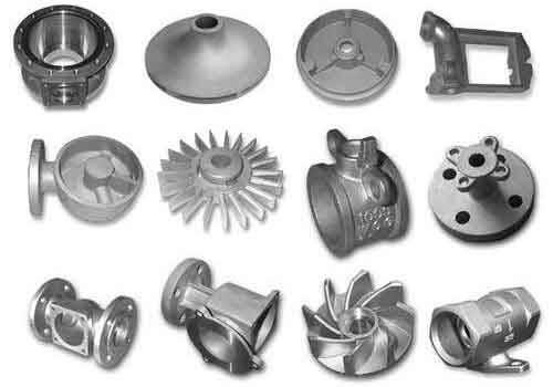
Phase 1: The Foundational Stage – Structural Design
The journey of a quality sand casting part begins long before metal is poured. As a consultant to design engineers, I always emphasize that the designer must be intimately familiar with relevant standards and the current state of casting technology. The selection of the manufacturing process—in this case, sand casting—and the appropriate alloy (e.g., Al-Si-Mg systems like A356/A357 or high-strength alloys like 206.0) are critical first decisions. The casting’s design must inherently be “friendly” to the sand casting process. This involves optimizing geometries to avoid sharp corners, promote uniform wall thickness, facilitate mold assembly and core placement, and ensure proper feeding during solidification. A formalized Concurrent Engineering process, where manufacturing review is a mandatory gate before design release, is a powerful monitoring tool. The core control element here is the castability or manufacturability of the design. We employ checklists and design rule software to quantify this. For instance, the feasibility of a section can be assessed by ensuring the modulus (Volume/Surface Area) is conducive to directional solidification. A simple check for minimum recommended wall thickness for aluminum sand casting parts in various size ranges is summarized below:
| Part Envelope Size (mm) | Minimum Practical Wall Thickness (mm) |
|---|---|
| < 100 | 3.0 – 4.0 |
| 100 – 250 | 4.0 – 5.0 |
| 250 – 500 | 5.0 – 6.5 |
| > 500 | 6.5 – 8.0+ |
Phase 2: The Blueprint for Success – Process Design
Once a castable design is frozen, my focus shifts to crafting the manufacturing blueprint—the casting process design. A superior process plan balances simplicity, efficiency, and robustness to produce sound sand casting parts. This involves determining parting lines, designing gating and feeding systems (risers and chills), specifying core designs, and calculating process parameters. The scientific basis for this often relies on thermal and fluid flow principles. For example, Chvorinov’s Rule governs the solidification time of a casting section:
$$ t = C \left( \frac{V}{A} \right)^n $$
where \( t \) is the solidification time, \( V \) is the volume of the section, \( A \) is its surface area, \( C \) is a mold constant, and \( n \) is an exponent (typically ~2). This rule is fundamental for riser sizing to ensure it solidifies after the casting. Today, we heavily rely on Casting Simulation Software (CAD/CAE) to virtually analyze mold filling, solidification, and predict defects like shrinkage porosity, enabling us to optimize the process digitally before any tooling is made. The control elements are the scientific validity and practical robustness of the process. The monitoring手段 is a strict protocol of peer review, simulation validation, and approval sign-offs. A summary of key design calculations is essential:
| System Component | Primary Design Calculation/Principle | Key Variable |
|---|---|---|
| Gating System | Bernoulli’s Theorem & Continuity Eq. | Pouring Time, Gate Area |
| Riser (Feeder) | Modulus Method (V/A ratio) | Riser Volume, Contact Modulus |
| Chill Design | Heat Transfer Rate (Fourier’s Law) | Chill Mass, Contact Area |
Phase 3: The Physical Replica – Pattern and Core Box Manufacturing
The process design is rendered physical through patterns and core boxes. The accuracy and finish of these tools directly transfer to the mold cavity and hence to the final sand casting parts. Depending on the production volume, patterns can be made from wood, plastic, or metal. Control elements include dimensional accuracy (accounting for shrinkage allowances), surface finish, adequate draft angles, and structural integrity. The monitoring手段 is a first-article inspection against the tooling drawings, using Coordinate Measuring Machines (CMM) for critical dimensions. The required patternmaker’s shrinkage allowance for aluminum alloys is typically around 1.3% to 1.5%, but it must be precisely applied based on the specific alloy and part geometry. The relationship is:
$$ L_{pattern} = L_{casting} \times (1 + \alpha) $$
where \( L_{pattern} \) is the pattern dimension, \( L_{casting} \) is the desired final casting dimension, and \( \alpha \) is the total linear shrinkage allowance factor (incorporating liquid contraction, solidification contraction, and solid contraction).
Phase 4: The Raw Material Gateway – Incoming Material Control
The quality of input materials sets a ceiling on the quality of output sand casting parts. We implement a rigorous supplier qualification and material certification program. For aluminum casting, the primary raw material is primary or secondary aluminum ingot. Control elements are: chemical composition, metallurgical structure (grain size, inclusion content), and gas content (hydrogen). Monitoring involves certificate of analysis (CoA) review and periodic in-house verification. We use Spectrometry for composition, and a Reduced Pressure Test (RPT) or Telegas meter for hydrogen assessment. The solubility of hydrogen in molten aluminum follows Sieverts’ Law:
$$ S = k \sqrt{P_{H_2}} $$
where \( S \) is the solubility, \( k \) is a temperature-dependent constant, and \( P_{H_2} \) is the partial pressure of hydrogen. This highlights the critical need to control moisture in the environment and charge materials. A standard acceptance criteria for key elements in A356.2 alloy for critical sand casting parts might be:
| Element | Specification Range (wt.%) | Criticality for Sand Casting Parts |
|---|---|---|
| Si | 6.5 – 7.5 | Fluidity, Feeding Characteristics |
| Mg | 0.25 – 0.45 | Strengthening (via heat treatment) |
| Fe (max) | 0.12 | Controls brittle intermetallic phases |
| Ti | 0.04 – 0.20 | Grain refinement |
Phase 5: The Crucible of Transformation – Melting and Melt Treatment
This is arguably the most sensitive special process in making aluminum sand casting parts. Here, details are paramount. The sequence involves charging, melting, alloying, degassing (hydrogen removal), and modification (for Si-rich alloys). Each step has critical parameters. We monitor and control: melt temperature profile, composition via炉前spectroscopy, degassing efficiency via density index measurement, and modification effectiveness via thermal analysis. For degassing with rotary argon impellers, the rate of hydrogen removal can be modeled as a first-order reaction:
$$ \frac{dC}{dt} = -k (C – C_e) $$
where \( C \) is the instantaneous hydrogen concentration, \( C_e \) is the equilibrium concentration under the purge gas, \( k \) is a rate constant dependent on gas flow rate and bubble distribution. We target a density index below 0.2 for premium quality sand casting parts. For eutectic modification in Al-Si alloys, the thermal analysis curve provides a fingerprint; the depression of the eutectic temperature plateau (\( \Delta T \)) indicates the level of modification:
$$ \Delta T = T_{eutectic(unmod)} – T_{eutectic(measured)} $$
A \( \Delta T \) of 6-10°C typically indicates good modification with Sr or Na. The comprehensive melt control log for a heat of A356 would include:
| Process Step | Control Parameter | Target/Standard | Monitoring Tool |
|---|---|---|---|
| Melting | Maximum Superheat | ≤ 750°C | Calibrated Thermocouple |
| Alloying | Elemental Recovery | Per yield curves | Spectrometer Check |
| Degassing | Argon Flow Rate & Time | e.g., 15 L/min for 8 min | Flow Meter, Density Index Tester |
| Modification | Sr Addition & Hold Time | e.g., 150-200 ppm Sr, 15 min | Thermal Analysis Unit |
| Final Check | Hydrogen Level, Temp. | DI < 0.2, Pouring Temp. ±10°C | Density Tester, Thermocouple |
Phase 6: The Mold Matrix – Sand Preparation and Control
The mold is the negative of our final product. The properties of the sand mixture determine the surface finish, dimensional accuracy, and the occurrence of defects like sand inclusions, blows, or veining in sand casting parts. We use synthetic bonded sands (e.g., silica sand with furan or phenolic urethane binders). The control elements are: sand grain distribution (AFS Fineness Number), binder and catalyst percentages, moisture content, and the resulting cured properties like tensile strength and permeability. Regular testing with a sand lab is mandatory. The compactability and strength are often empirically correlated. A fundamental relationship for gas flow is given by Darcy’s Law, relevant to mold permeability:
$$ Q = \frac{k A \Delta P}{\mu L} $$
where \( Q \) is the volumetric flow rate of gas, \( k \) is the permeability of the sand, \( A \) is the area, \( \Delta P \) is the pressure drop, \( \mu \) is the gas viscosity, and \( L \) is the length. High permeability is crucial to allow gases from the binder decomposition and mold moisture to escape. A typical sand control sheet for a furan no-bake system producing heavy-section sand casting parts is:
| Property | Test Method | Control Limits | Frequency |
|---|---|---|---|
| AFS Grain Fineness No. | Sieve Analysis | 50 – 55 | Per sand delivery |
| Active Clay / LOI | Loss on Ignition | < 0.5% | Daily |
| Binder Addition | Weight Control | 1.0 – 1.3% (of sand) | Continuous |
| Catalyst Addition | Weight Control | 30 – 50% of binder | Continuous |
| Strip Time | Core/Bench Test | 15-25 min | Every 2 hours |
| Tensile Strength (24h) | Dog-bone Test | > 250 psi | Twice per shift |
| Permeability | Perm Meter | > 120 | Twice per shift |
Phase 7: Building the Negative – Molding and Coremaking
This is where the plan becomes physical mold assemblies. Consistency in操作 is key. Control elements include: mold hardness (a measure of compaction uniformity), accurate placement of cores, chills, and filters, and verification of core and mold dimensions. We use mold hardness testers (Brinell or Green Hardness type) and perform periodic layout inspections on first-off mold assemblies using gauges to check critical wall thicknesses of the future sand casting parts. The required mold hardness depends on the casting geometry and pouring height; a general guideline is:
$$ H_m \propto \frac{\rho g h}{\sigma_s} $$
where \( H_m \) is the required mold hardness, \( \rho \) is the metal density, \( g \) is gravity, \( h \) is the metallostatic head, and \( \sigma_s \) is the sand’s compressive strength. This underscores the need for higher hardness in deep molds to resist metal pressure and avoid mold wall movement.
Phase 8: The Moment of Truth – Pouring and Solidification
Whether using gravity pouring or counter-gravity (low-pressure) techniques, this phase transfers the liquid metal into the mold cavity. For gravity pouring of sand casting parts, we control pouring temperature and pouring time (or rate). For low-pressure casting, which offers superior filling control for certain geometries, we precisely control the pressure-time profile. The fundamental equation for low-pressure filling is derived from balancing the pressure head with the system’s hydraulic characteristics:
$$ P(t) = \rho g h(t) + \frac{1}{2} \rho v(t)^2 + \Delta P_{losses} $$
where \( P(t) \) is the applied furnace pressure, \( h(t) \) is the rising metal height in the stalk and mold, \( v(t) \) is the metal velocity, and \( \Delta P_{losses} \) accounts for friction and other losses. A well-designed profile ensures non-turbulent, laminar filling—critical for avoiding oxide entrapment in aluminum sand casting parts. The control element is strict adherence to the validated pouring parameters. Monitoring involves calibrated pyrometers for temperature and data loggers for pressure curves.
Phase 9: The Final Verification – Casting Inspection and Testing
After shakeout, cleaning, and heat treatment (if applicable), the sand casting parts undergo comprehensive evaluation. This three-pronged approach assesses: 1) Dimensional and Visual Quality: Using fixtures, CMMs, and visual inspection per ASTM E155 standards for reference radiographs. 2) Internal Soundness: Employing non-destructive testing (NDT) like X-ray radiography or ultrasound to detect shrinkage, inclusions, or cracks. The intensity of an X-ray beam attenuates through a casting as per the Beer-Lambert law, helping to identify density variations:
$$ I = I_0 e^{-\mu x} $$
where \( I \) is the transmitted intensity, \( I_0 \) is the initial intensity, \( \mu \) is the linear attenuation coefficient, and \( x \) is the material thickness. 3) Metallurgical and Mechanical Properties: This involves chemical analysis, tensile testing, and metallography to verify microstructure (e.g., SDAS – Secondary Dendrite Arm Spacing, which correlates with mechanical properties and is modeled by:
$$ \lambda_2 = a (t_f)^n $$
where \( \lambda_2 \) is the SDAS, \( t_f \) is the local solidification time, and \( a, n \) are constants. A summary of inspection methods for a high-performance aluminum sand casting part is:
| Quality Aspect | Typical Defects Sought | Inspection Method(s) | Acceptance Standard |
|---|---|---|---|
| Dimensional | Warpage, Core Shift | CMM, Functional Gauges | Drawing GD&T Tolerances |
| Surface | Cold Shuts, Sand Inclusions | Visual, Dye Penetrant (PT) | ASTM E125 / Customer Spec |
| Internal | Shrinkage, Porosity, Inclusions | X-Ray Radiography (RT) | ASTM E155 (Level 2-3) |
| Mechanical | Low Strength, Elongation | Tensile Test (ASTM B557) | Min. UTS, YS, % Elong. |
| Metallurgical | Poor Microstructure, Phases | Metallography (ASTM E3) | Grain Size, SDAS, Phase Limits |
Conclusion: The Synergistic System
In my career dedicated to perfecting the manufacture of sand casting parts, I have observed that excellence is never accidental. It is the direct result of a consciously designed and diligently managed system that views quality as a thread woven through every lifecycle phase. Advanced tools like simulation and real-time process monitoring are invaluable, but they must be built upon the foundation of sound principles in design, materials science, and process engineering. The integrated strategy detailed here—encompassing proactive design review, scientific process planning, stringent raw material and process control, and comprehensive verification—creates a robust framework. This framework not only ensures the delivery of reliable, high-performance sand casting parts but also fosters continuous improvement, driving down costs and enhancing competitiveness. Ultimately, every successful sand casting part is a testament to the meticulous control exercised at each step of its creation.