Lost foam casting (LFC) is a revolutionary casting method that has gained significant popularity in the manufacturing industry due to its numerous advantages. This casting technique offers benefits such as low production costs, excellent surface quality, high dimensional accuracy, and minimal environmental pollution. However, designing the casting process for LFC is more challenging compared to sand casting due to the presence of negative pressure during the casting process, which significantly affects the filling and cooling stages. In this article, we will explore the application of casting simulation technology in the development of the LFC process, using the example of a tractor transmission case.
Product Introduction
The transmission case shell is a crucial component of a certain type of tractor transmission system. The theoretical weight of the blank is 265.1 kg (with a density of 7.3 x 10³ kg/m³), and the maximum external dimensions are 816 mm x 530 mm x 578 mm. The minimum wall thickness of the cavity is approximately 14 mm, and the maximum wall thickness is about 50 mm. The overall size of the box is large, while the wall thickness is small. When using LFC, the deformation problem is of primary concern, followed by the cold shut issue. Deformation can be controlled through strict process management, reasonable gating system and anti-deformation measures, as well as a proper sand molding process. Cold shuts can be addressed by selecting a reasonable gate location and using a higher pouring temperature.
Process Design
To ensure the efficiency and success rate of future process trials, three LFC process schemes were designed and simulated to evaluate the rationality of the process plans. The three schemes are as follows:
Scheme 1: Horizontal Top Pouring Process
- Straight runner diameter: 50 mm
- Cross runner section: 40 mm x 20 mm
- Ingate section: 40 mm x 7.5 mm
- Head pressure: 210 mm
Scheme 2: Inclined Side Pouring Process
- Straight runner diameter: 50 mm
- Cross runner section: 60 mm x 55 mm
- Ingate section: 55 mm x 15 mm
- Head pressure: 190 mm
Scheme 3: Vertical Top Pouring Process
- Straight runner diameter: 50 mm
- Cross runner section: 45 mm x 50 mm
- Ingate section: 60 mm x 15 mm
- Head pressure: 320 mm
The Huazhu CAE casting simulation system’s lost foam simulation module was used to simulate these three process schemes, and the results are shown in the following figures:
Simulation Results of Scheme 1: In the later stage of solidification, slag inclusion and shrinkage defects appeared at the marked positions in the figure, and an overflow structure needed to be added. Additionally, due to the horizontal placement, the flat part of the part was at the bottom, which easily caused the collapse of the box. Therefore, during the vibration and compaction process, it was necessary to add sand and vibrate in multiple steps, and pour quickly during the pouring process. Moreover, due to the size limitation, only one part could be placed in one box, resulting in a smaller box weight.
Simulation Results of Scheme 2: Compared with Scheme 1, Scheme 2 had a smaller tendency for slag inclusion and shrinkage, and also reduced the risk of box collapse. However, the inclined placement increased the difficulty of sand addition and vibration compaction, requiring multiple sand additions and low-amplitude, high-frequency vibration compaction. Similarly, due to the size influence, only one part could be placed in one box, and the box weight was small.
Simulation Results of Scheme 3: Scheme 3 had the same characteristics as Scheme 2 and could achieve one-box-two-parts pouring, with a larger box weight and higher efficiency, but the filling was more chaotic.
| Scheme | Advantages | Disadvantages |
|---|---|---|
| 1 | Simple structure | Slag inclusion, shrinkage defects, risk of box collapse, one-part-per-box, low box weight |
| 2 | Smaller defects tendency, reduced box collapse risk | Difficult sand addition and vibration compaction, one-part-per-box, low box weight |
| 3 | One-box-two-parts pouring, higher efficiency | Chaotic filling |
Process Optimization
Considering the advantages and disadvantages of the three process schemes and the actual situation of the lost foam production line, the process scheme shown in Figure 7 was adopted after comprehensive analysis, and the module assembly and pouring tests were carried out.
- Straight runner diameter: 50 mm
- Cross runner section: 60 mm x 55 mm
- Ingate section: 55 mm x 15 mm
- Head pressure: 190 mm
Process Experiment
The process flow included: bead pre-expansion -> pattern molding -> pattern assembly -> coating -> drying -> molding and pouring -> cleaning.
A one-box-one-part scheme was adopted, and the molten iron entered from the top of the casting, with an overflow block added at the top.
The molding method is shown in Figure 9, with the following parameters:
- Number of parts per box: 1
- Bottom sand thickness: 100 mm
- Surface sand thickness: 30 mm
- Pouring temperature: 1490 – 1510 °C
- Negative pressure intensity: 5.5 MPa – 6 MPa
- Designed pouring time per box: 90 s
- Holding pressure time: ≥ 20 min
After shot blasting and cleaning, the surface quality of the casting was good, and no obvious defects were observed. The hardness of the end face was 180 – 190 HB.
Detection and Machining
A three-dimensional scanner was used to scan the sample blank to obtain the three-dimensional model of the blank. By comparing the full-size of the blank’s three-dimensional model with the theoretical three-dimensional model, the deformation and machining allowance of the blank were detected, and the results are shown in Figure 11.
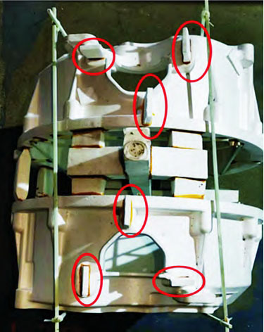
To further verify the deformation and machining situation of the sample blank, it was processed and evaluated. The results showed that the deformation of the sample was small, within the process control range, and no other defects were found, indicating that the sample was qualified. The processed product is shown in Figure 12.
After comparison, the three-dimensional model of the blank almost perfectly matched the theoretical model, and no areas with large deformations were found. The deformation was within the process control range.
Conclusion
The development cycle of new products in lost foam casting is relatively long. By using the casting simulation system to simulate the proposed process during the process design stage, technicians can intuitively analyze the advantages and disadvantages of each process scheme, which is convenient for later process optimization. The use of the casting simulation system in the process design stage greatly improves the development efficiency of new products and shortens the trial production cycle. For the transmission case shell described in this article, at least three process tests would be required following the traditional process development approach, while using the scheme described in this article, only one process test was conducted to achieve success, demonstrating significant advantages in terms of cost, cycle, and efficiency.
References:
[1] Lü Kehua, Li Zengmin, Li Lixin, et al. Application and Analysis of Casting Numerical Simulation Technology in Lost Foam Casting [J]. Foundry Equipment and Technology, 2012(4): 38 – 40.
[2] Zhang Leilei, Li Fengjun, Cai Anke, et al. Virtual Reality Visualization Application of Lost Foam Casting Filling Process Simulation [J]. Foundry, 2015, 64(6): 550 – 551 + 554.
[3] Deng Hongyun, Yin Shihe, Zhang Zhou, et al. Handbook of Lost Foam Casting and Full Mold Casting Technology [M]. Beijing: Mechanical Industry Press, 2012: 32 – 34.
[4] Zhu Lijuan, Du Dexi, Dong Xiuqi, et al. Selection of Gating System for Lost Foam Casting [J]. Foundry, 2006, 55(12): 1319 – 1321.
In addition to the above content, we can further expand the discussion on lost foam casting and its applications. For example, we can explore the factors that affect the quality of lost foam castings, such as the properties of the foam pattern, the pouring temperature, and the vacuum degree. We can also compare lost foam casting with other casting methods, such as gravity casting, to highlight the unique advantages of lost foam casting.
Let’s start by discussing the factors that affect the quality of lost foam castings. The quality of the foam pattern is crucial, as it directly affects the dimensional accuracy and surface quality of the casting. The foam pattern should have good strength, dimensional stability, and thermal decomposition properties to ensure that it can withstand the casting process without deformation or damage. The pouring temperature also plays an important role. If the pouring temperature is too high, it may cause excessive decomposition of the foam pattern, resulting in defects such as slag inclusion and porosity. On the other hand, if the pouring temperature is too low, it may lead to poor fluidity of the molten metal, causing cold shuts and other defects. The vacuum degree during the casting process is another important factor. A proper vacuum degree can help to remove gases and impurities from the molten metal, improving the density and mechanical properties of the casting.
Now, let’s compare lost foam casting with gravity casting. Gravity casting is a traditional casting method that relies on the force of gravity to fill the mold with molten metal. Compared to gravity casting, lost foam casting has several advantages. First, lost foam casting can produce castings with complex shapes and thin walls, which is difficult to achieve with gravity casting. Second, lost foam casting offers better dimensional accuracy and surface quality, as the foam pattern can closely match the shape of the casting, reducing the need for subsequent machining. Third, lost foam casting has a lower environmental impact, as it generates less waste and requires less energy consumption.
To illustrate these points, let’s take a look at the following table:
| Casting Method | Advantages | Disadvantages |
|---|---|---|
| Lost Foam Casting | Complex shape casting, good dimensional accuracy, excellent surface quality, low environmental impact | Higher initial cost, requires specialized equipment |
| Gravity Casting | Simple process, low cost | Limited to simpler shapes, lower dimensional accuracy |
In conclusion, lost foam casting is a promising casting technology that offers many advantages over traditional casting methods. By using casting simulation technology, we can optimize the process design and improve the quality of the castings. Further research and development in this field will undoubtedly lead to more advanced and efficient casting processes, meeting the increasing demands of the manufacturing industry.
The Development History of Lost Foam Casting
Lost foam casting has a relatively short but significant development history. It originated in the 1950s and has since undergone continuous improvements and innovations.
In the early stages, lost foam casting was mainly used in the production of small and simple castings. The process was relatively crude, and the quality of the castings was not very stable. However, researchers and engineers continued to explore and optimize the technology, gradually improving its performance and applicability.
In the 1980s and 1990s, significant progress was made in lost foam casting. The development of computer simulation technology allowed for more precise control and optimization of the casting process. This enabled manufacturers to predict and prevent potential defects, improving the quality and reliability of the castings.
During this period, the use of lost foam casting began to expand to more complex and larger castings. It was increasingly adopted in various industries, such as automotive, aerospace, and machinery, due to its ability to produce castings with intricate shapes and good dimensional accuracy.
In the 21st century, lost foam casting has continued to evolve. Advances in materials science have led to the development of new types of foam patterns and coatings, further improving the quality and performance of the castings. Additionally, the integration of automation and robotics in the production process has increased the efficiency and consistency of lost foam casting.
Today, lost foam casting is a mature and widely used casting technology. It offers numerous advantages, including the ability to produce near-net-shape castings, reduce material waste, and improve production efficiency. However, like any technology, it still faces some challenges, such as the need for further improvement in the control of process parameters and the development of more efficient and environmentally friendly materials.
Looking to the future, we can expect further advancements in lost foam casting. Continued research and development will likely focus on improving the quality and properties of the castings, reducing costs, and enhancing the sustainability of the process. New applications and markets may also emerge as the technology continues to evolve.
To summarize the development history of lost foam casting, we can use the following table:
| Period | Key Developments |
|---|---|
| 1950s – 1970s | Emergence of the technology, used for small and simple castings |
| 1980s – 1990s | Progress in computer simulation, expansion to more complex castings, adoption in various industries |
| 21st Century | Advances in materials science, integration of automation, continued evolution and improvement |
In conclusion, lost foam casting has come a long way since its inception and has become an important casting technology in the modern manufacturing industry. Its development history is a testament to the continuous efforts of researchers and engineers to improve and innovate in this field.