
In my own process development work, I treat a diesel engine block as one of the most demanding candidates for lost foam casting. The block is not a simple prismatic part. It combines cylinder bores, water jackets, oil galleries, main bearing bulkheads, camshaft or balance shaft features, stiffening ribs, flanges, and many small holes that must survive filling and solidification without distortion, gas defects, or incomplete filling. When I compare lost foam casting with conventional green sand, resin sand, or shell molding for this family of parts, I see a clear economic and technical case, but only if the pattern, coating, gating, sand, vacuum, and metal chemistry are controlled as one integrated system. My experience is that lost foam casting can deliver a near-net-shape diesel engine block with high dimensional repeatability, reduced cleaning, lower machining allowance, and excellent surface finish, provided that the process window is defended with data rather than opinion.
The central idea of lost foam casting is straightforward: a foam pattern that matches the casting geometry, adjusted for alloy shrinkage, remains inside the mold during pouring. Molten metal enters the mold, vaporizes the foam, and replaces the pattern volume. Because the pattern is not withdrawn, the mold does not need a parting line in the traditional sense, and the sand does not need binder, water, or organic additives. This is why lost foam casting is often described as a green casting route. In my view, however, the word “green” should not be misunderstood as “simple.” The process is green because dry sand can be reused, binder-related emissions are low, and cleaning room labor is reduced, but the process physics are complex. Gas generation, pattern degradation, coating permeability, sand compaction, vacuum level, metal velocity, and cooling rate all interact.
For diesel engine blocks, the value of lost foam casting comes from the ability to form internal and external features with a single pattern cluster. The foam pattern can include the water jacket, oil passages, and other details that would normally require cores. This reduces core-making, core-setting, moulding, and core-related scrap. It also reduces the number of sand systems that must be controlled. I have found that a well-designed lost foam casting process for an engine block can achieve a casting yield above 90 percent, a first inspection pass rate above 95 percent, and a machining pass rate near 99 percent. These numbers are not automatic. They are the result of disciplined pattern design, density control, coating control, gating design, vacuum control, and metal treatment.
The following sections describe the method I use to develop a diesel engine block through lost foam casting. I present the reasoning, the process windows, the equations I use for first-pass calculations, and the tables that summarize the important variables. My goal is not to describe a single fixed recipe, but to show how the variables interact so that a robust lost foam casting process can be established for different block sizes and wall thicknesses.
Why Lost Foam Casting Fits the Diesel Engine Block
A diesel engine block has a high ratio of internal complexity to external envelope. The cylinder bores require consistent wall thickness between the water jacket and the combustion chamber. The main bearing area requires stiffness and soundness. The oil galleries require clean internal passages. The outer walls often include ribs, bosses, and flanges that must be dimensionally stable. In conventional sand casting, these features require multiple cores and careful core assembly. Core shift, core gas, veining, burn-on, and sand inclusion are common concerns. In lost foam casting, the foam pattern carries the geometry, so the sand is only a supporting medium. This removes many core-related defects but introduces new ones related to foam decomposition and gas evacuation.
I use several criteria when deciding whether a diesel engine block is a good candidate for lost foam casting. The first is section thickness. The block should have a dominant wall thickness range that can be fed and cooled without excessive thermal gradients. The second is pattern collapsibility. Deep pockets and blind holes must be arranged so that foam gas can escape through the coating and sand before the metal front arrives. The third is coating access. If a region cannot be coated uniformly, it is a risk. The fourth is sand access. If dry sand cannot flow into a cavity and compact under vibration, the local mold strength will be insufficient. The fifth is gating access. The gating system must be able to deliver metal to all critical regions without excessive turbulence or cold shut.
| Feature | Lost Foam Casting Opportunity | Main Risk | My Control Measure |
|---|---|---|---|
| Cylinder water jacket | Formed directly by foam pattern; no separate core | Coating bridging, gas entrapment | Coating viscosity control and venting through pattern design |
| Oil galleries | Integral passages from pattern assembly | Residual foam ash or coating debris | High permeability coating and thorough shakeout |
| Main bearing bulkheads | Thick sections fed through controlled gating | Shrinkage porosity | Chill placement, riser design, and carbon equivalent control |
| External ribs and flanges | Near-net shape, reduced machining | Distortion during cooling | Uniform wall design and sand support |
| Small holes and bosses | Formed by foam, no drilling in many cases | Incomplete fill or coating blockage | Minimum hole diameter rules and local gating |
When I apply lost foam casting to a diesel engine block, I do not treat the foam pattern as a consumable that can be made to loose tolerances. The pattern is part of the mold. Its density, fusion, dimensional accuracy, surface finish, and adhesive joints determine the final casting. In my experience, 50 to 60 percent of the success of lost foam casting depends on foam pattern quality. Another 30 percent depends on coating and coating application. The remaining 10 to 20 percent depends on sand, vacuum, melting, pouring, and cooling. These percentages are approximate, but they remind me where to focus when a defect appears.
Pattern Design and Die Strategy
I begin pattern design by defining the parting and slicing strategy. For a diesel engine block, horizontal slicing is usually the most practical because it allows each foam section to be molded in a simple die and then assembled into a full pattern cluster. The key requirement is that every section must release from its die without tearing, dragging, or excessive ejection distortion. The intake and exhaust passages, water jacket openings, and crankcase features must be arranged so that the die opening direction is compatible with the local geometry.
I prefer a horizontal split that separates the block into logical layers: the upper deck and cylinder head interface, the cylinder barrel and water jacket region, the main bearing and crankcase region, and the oil pan flange region. Each layer can be molded separately and then glued with cold adhesive or hot melt adhesive. The crankcase area often needs special treatment. If the crankcase is left as a deep open pocket, the foam pattern may be weak and the sand may not compact well. I therefore use a local closing strategy: the crankcase is closed along the draw direction, and the outer wall is relieved with an equal-wall-thickness hollow recess. This keeps the pattern stiff, allows sand to flow, and reduces the risk of coating bridging.
I calculate the pattern dimensions from the casting drawing using a shrinkage allowance. For a given casting dimension \(L_c\) and a measured or assumed linear shrinkage \(S\), the pattern dimension \(L_p\) is:
$$L_p = \frac{L_c}{1 + S}$$
Alternatively, if I am starting from the pattern and want to predict the casting size, I use:
$$L_c = L_p (1 + S)$$
For ductile iron and gray iron, the linear shrinkage depends on section thickness, restraint, and carbon equivalent. For the low-alloy gray iron used in diesel engine blocks, I typically use a pattern shrinkage allowance between 0.8 percent and 1.0 percent, but I verify it with casting trials. The water jacket and thin ribs may require a slightly different allowance than the main bearing bulkheads because they cool at different rates. I therefore keep a shrinkage table by feature type rather than using a single global value.
| Block Feature | Typical Casting Wall Thickness | Pattern Shrinkage Allowance | Reason |
|---|---|---|---|
| Cylinder bore wall | 6–10 mm | 0.8–0.9% | Restrained by water jacket and deck |
| Water jacket wall | 4–7 mm | 0.7–0.9% | Thin section, faster cooling |
| Main bearing bulkhead | 20–40 mm | 0.9–1.1% | Thick section, higher thermal mass |
| Outer rib and flange | 5–12 mm | 0.8–1.0% | Moderate restraint |
| Oil gallery passage | 6–12 mm | 0.8–1.0% | Internal passage, coating dependent |
I also apply a wall thickness rule for foam pattern strength. If a foam section is too thin, it may break during ejection or handling. If it is too thick, it may cool slowly and produce a coarse surface. For lost foam casting, I usually keep the minimum foam wall at 3.5 to 4 mm for a diesel engine block, unless the geometry is fully supported by sand. Holes below a certain diameter are better drilled later because the foam pattern may not fill completely or the coating may close the passage. I use a minimum as-cast hole diameter of 8 to 10 mm for general passages and larger for critical oil galleries.
The die itself must be designed for uniform bead fusion. I prefer aluminum tooling with conformal cooling lines and multiple steam and vent ports. The die surface should be polished in the direction of ejection. Draft angles are usually 1 to 3 degrees, but I increase draft in deep pockets. Ejector pins must be placed on strong bosses or hidden surfaces. If ejector pins are placed on a thin wall, the pattern will dimple, and the dimple will appear on the casting. I also design the die with a slight expansion allowance because the foam pattern will shrink after molding. This shrinkage is different from the metal shrinkage and must be handled separately.
Foam Material, Pre-Expansion, and Maturation
For diesel engine blocks, I use expandable polystyrene beads with a controlled bead size distribution. The bead size affects fill of thin sections, surface finish, and fusion. A smaller bead gives better surface detail and thinner wall capability, but it may require more careful pre-expansion and can trap more moisture. A larger bead gives better fusion and lower density, but it may not fill narrow ribs or small bosses. I select a bead grade that balances fillability and fusion for the smallest feature in the block.
The density of the foam pattern is one of the most important variables in lost foam casting. If the density is too low, the pattern may be weak, the surface may be rough, and the amount of gas generated may be low but the pattern may collapse prematurely. If the density is too high, the pattern is stronger, but it generates more gas, produces more residue, and may cause gas defects, cold shut, or incomplete filling. I control the molded pattern density to a narrow window. For the diesel engine block, I target a molded density of 23 to 24 g/L. To achieve that, I control the pre-expanded bulk density to 20 to 21 g/L.
The relationship between pre-expanded bulk density and molded density is not perfectly fixed because it depends on the molding cycle, steam pressure, and die venting. I treat it as a calibration curve. If the pre-expanded bulk density is \(\rho_b\) and the molded density is \(\rho_m\), I can define an effective densification factor \(k\):
$$\rho_m = k \rho_b$$
From my trials, \(k\) usually falls between 1.08 and 1.18 for the block pattern. I verify \(k\) for each bead lot and each molding machine. I measure the pattern density by weighing a representative section and dividing by its volume:
$$\rho_m = \frac{m_p}{V_p}$$
The pre-expansion process must produce beads with a narrow density distribution. If the distribution is too wide, some beads will be under-expanded and some over-expanded. Under-expanded beads contain more blowing agent and can cause post-expansion or surface blisters. Over-expanded beads may collapse and create voids. I use a pre-expansion temperature and time that produce a stable bulk density, and I avoid overheating the beads. After pre-expansion, the beads must be matured in a ventilated silo. Maturation allows the blowing agent to redistribute and the bead surface to stabilize. I mature the beads for 4 to 8 hours before molding. For some bead lots, I extend maturation to 12 hours if the density is drifting.
| Variable | Target | Acceptable Range | Measurement Method |
|---|---|---|---|
| Raw bead size | Selected for thin-wall fill | Lot-specific | Supplier sieve data and trial molding |
| Pre-expanded bulk density | 20–21 g/L | 19.5–21.5 g/L | Density cup and scale |
| Maturation time | 4–8 h | 4–12 h | Time log and density check |
| Molded pattern density | 23–24 g/L | 22.5–24.5 g/L | Weight and volume of representative section |
| Moisture after molding | Low and uniform | As low as practical | Drying curve and weight loss |
I also control the blowing agent content. If the blowing agent remains too high, the pattern may continue to expand after molding and distort. If it is too low, the beads may not fuse. I use a combination of maturation time, drying, and storage temperature to stabilize the pattern. In my practice, the pattern is not ready for assembly immediately after molding. It needs time for dimensional stabilization.
Pattern Molding and Dimensional Control
I use a hydraulic semi-automatic molding machine for the diesel engine block pattern sections. The machine must deliver repeatable steam pressure, cooling water, and vacuum. The molding cycle has several stages: die closing, steam heating, pressure holding, cooling, vacuum, die opening, and ejection. Each stage affects bead fusion, surface quality, and dimensional accuracy. I have found that the most common cause of poor pattern quality is not the bead itself but an inconsistent molding cycle.
For a complex block pattern, I prefer to mold the cylinder barrel and crankcase sections in one tool if the geometry allows. This reduces the number of adhesive joints and improves dimensional accuracy. However, it also increases tooling cost and requires careful die design for uniform steam distribution. If the block is too complex, I divide it into sections that can be molded reliably and then assemble them with fixtures. The fixture is critical. I do not rely on operator judgment for the position of the water jacket, cylinder bores, and main bearing seats. I use locating pins or nesting features in the foam sections so that the assembled pattern is dimensionally correct.
The molded pattern must be measured before assembly. I check the following dimensions: overall length, overall width, overall height, cylinder bore spacing, water jacket thickness, main bearing bore position, deck flatness, and oil pan flange position. I use a coordinate measuring machine or a dedicated checking fixture. If a pattern section is out of tolerance, I do not try to bend it into shape. I reject it. Bending a foam pattern introduces residual stress, and the pattern may relax during coating or pouring.
| Pattern Check | Nominal Dimension | Tolerance | Frequency |
|---|---|---|---|
| Overall length | Block-specific | ±0.5 mm | Every section |
| Overall width | Block-specific | ±0.5 mm | Every section |
| Overall height | Block-specific | ±0.5 mm | Every section |
| Cylinder bore spacing | Block-specific | ±0.3 mm | Every section |
| Water jacket thickness | 4–7 mm | ±0.4 mm | Sampling |
| Deck flatness | 0 mm | 0.3 mm max | Every section |
| Main bearing bore position | Block-specific | ±0.3 mm | Every section |
After molding, the pattern sections are stored in a controlled area. I keep them away from direct sunlight, heat sources, and drafts. The storage temperature should be stable because foam expands and contracts with temperature. If the pattern is stored in a cold area and then brought into a warm assembly area, it may grow. I allow the pattern to equalize to room temperature before measurement and assembly. This is especially important for large diesel engine block patterns because a small temperature change over a long dimension can exceed the tolerance.
Drying, Finishing, and Assembly
Moisture is an enemy of lost foam casting. Water in the foam pattern turns into steam, increases gas evolution, and can cause blowholes, cold shut, or coating spalling. After molding, I dry the pattern sections in a dedicated drying room. The drying conditions are typically 55 ± 5°C and relative humidity below 30 percent. I dry until the pattern weight stabilizes. For a large diesel engine block pattern, this may take several hours or even days, depending on section thickness and stacking arrangement. I do not stack patterns tightly during drying because air must circulate around every surface.
After drying, the pattern sections are aged at room temperature. Natural aging allows residual moisture and blowing agent to diffuse out. In my process, I require a minimum aging time of 20 days for engine block patterns. This is not a short cycle, but it is necessary for dimensional stability and defect avoidance. If the pattern is used too soon, it may shrink or warp after coating, and the adhesive joints may open. The aging area must be clean and protected from dust.
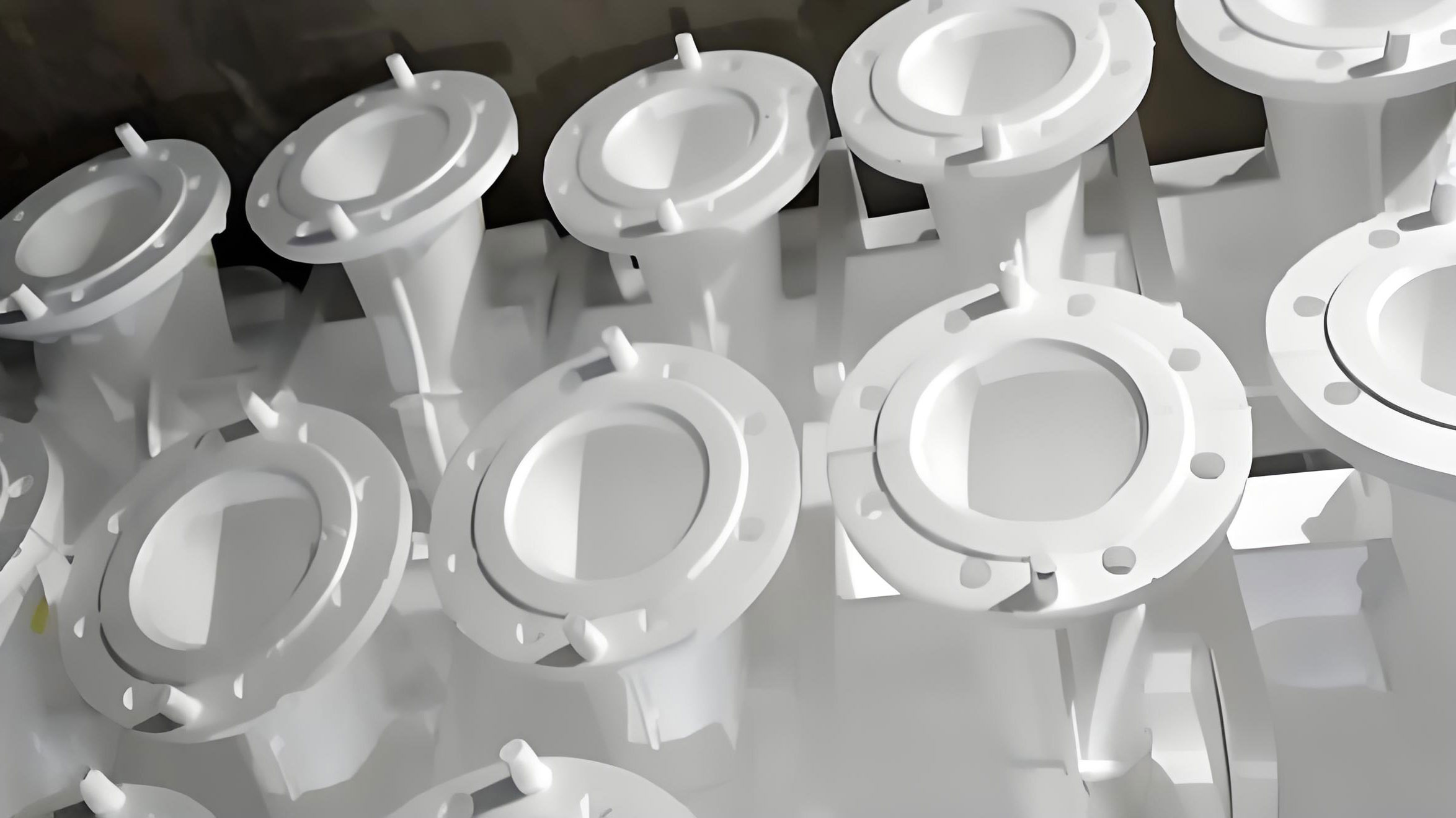
Finishing follows aging. I remove flash, parting line marks, and ejector pin marks. I repair damaged surfaces with a compatible foam filler or a small amount of fresh foam and adhesive. I check the critical geometry again. Then I assemble the pattern sections into a cluster. For a diesel engine block, the adhesive selection is important. I use cold adhesive for the large mating surfaces because it gives enough open time to position the sections accurately. I use hot melt adhesive for the gating system because it sets quickly and can be reworked. The adhesive must not attack the foam, must not leave a hard residue that can cause inclusions, and must decompose cleanly during pouring.
I apply adhesive sparingly and uniformly. Excess adhesive creates a hard, dense region that vaporizes more slowly than the foam. This can cause a cold spot, gas defect, or coating blister. I also use double-sided tape or a thin adhesive bead to seal the joints. Any gap between foam sections will fill with coating or sand, and that can create a fin or a sand inclusion. I inspect every joint before coating.
Coating System and Permeability
The coating is the interface between the foam pattern and the sand. In lost foam casting, the coating must do several things at once. It must be strong enough to support the sand and resist metal erosion. It must be permeable enough to allow foam decomposition gases to escape. It must be refractory enough to resist metal penetration. It must adhere to the foam pattern and not crack during handling or pouring. It must also be thin enough not to bridge small passages but thick enough to prevent sand burn-on. The coating is therefore a compromise, and the process window is narrow.
I use a commercial lost foam coating that is specifically formulated for gray iron and low-alloy iron. I apply it in two coats. The first coat is usually a slightly more permeable base coat, and the second coat is a smoother finish coat. The coating is applied by dipping or flow coating, depending on the pattern geometry. For a diesel engine block, I prefer dip coating with controlled drainage because it gives more uniform coverage in the water jacket and oil galleries. After each coat, the pattern is dried. The drying temperature and humidity must be controlled to prevent skinning or cracking.
I control coating thickness to 1.0 to 1.5 mm. If the coating is too thin, sand may penetrate the surface, causing burn-on and rough castings. If the coating is too thick, gas permeability decreases, and foam gas may be trapped, causing blowholes, cold shut, or incomplete filling. The coating thickness can be estimated from the weight gain:
$$t_c = \frac{\Delta m}{\rho_c A_s}$$
where \(\Delta m\) is the coating weight gain, \(\rho_c\) is the dry coating density, and \(A_s\) is the coated surface area. I use this equation for a quick check, but I also verify with a magnetic thickness gauge on flat test plates and with destructive sectioning on scrap patterns.
| Coating Variable | Target | Acceptable Range | Effect of Deviation |
|---|---|---|---|
| Coating thickness | 1.0–1.5 mm | 0.9–1.7 mm | Too thin: burn-on; too thick: gas defects |
| Coating density | Supplier specification | Controlled by mixing | Affects permeability and strength |
| Viscosity | Zahn cup specification | Narrow window | Affects drainage and coverage |
| Dry film permeability | High enough for gas escape | Supplier specification | Low permeability causes blowholes |
| Drying temperature | 55 ± 5°C | 50–60°C | Too high: cracks; too low: retained moisture |
| Relative humidity | < 30% | 20–35% | High humidity slows drying |
I also pay attention to coating coverage in blind areas. The water jacket is particularly challenging because it is narrow and deep. If the coating bridges between the inner and outer walls, the water jacket may be partially blocked. I use a borescope or a flow test on sacrificial patterns to verify that the coating has not closed the passage. If bridging is found, I reduce coating viscosity, increase drainage time, or modify the pattern to improve access.
Gating System Design
The gating system for a diesel engine block in lost foam casting must deliver metal quickly and smoothly. Because the foam pattern is vaporized by the metal, the gating system must also manage the gas generated at the metal front. If the metal enters too slowly, the foam may not vaporize completely, and the pattern may collapse ahead of the metal, causing a mold cavity collapse or a cold shut. If the metal enters too quickly, the flow may be turbulent, causing sand erosion, coating damage, and gas entrainment. I therefore design the gating system as a pressure-controlled filling system.
I use a closed gating system for the diesel engine block. In a closed system, the choke is at the sprue, and the runner and ingates are proportioned so that the runner is not fully pressurized. The typical ratio I use is:
$$A_s : A_r : A_g = 1 : 1.2 : 1.5$$
where \(A_s\) is the sprue cross-sectional area, \(A_r\) is the runner cross-sectional area, and \(A_g\) is the total gate area. For some block designs, I use a slightly more restrictive ratio:
$$A_s : A_r : A_g = 1 : 1.0 : 1.2$$
The choice depends on the filling time and the gas evolution rate. A more restrictive gating system gives a lower filling speed and less turbulence, but it may be too slow for thin walls. A less restrictive system fills faster, but it may generate more gas and cause coating erosion.
I place multiple ingates along the block to feed critical regions. The main bearing bulkheads, cylinder bores, and deck are the last regions to freeze, so they need adequate feed metal. I avoid a single large ingate because it creates a localized hot spot and a strong gas jet. Instead, I use several smaller ingates distributed along the length of the block. The ingate position is chosen so that the metal front progresses from the bottom to the top, pushing foam gas ahead of it and out through the coating and sand. This is especially important in the crankcase and water jacket.
The pouring time for a diesel engine block is typically 35 to 40 seconds for a two-block cluster. I estimate the pouring time using a practical relationship:
$$t_p = K \sqrt{W}$$
where \(t_p\) is the pouring time in seconds, \(W\) is the total metal weight in kilograms, and \(K\) is an empirical coefficient. For lost foam casting of gray iron engine blocks, \(K\) usually falls between 2.0 and 3.0. I calibrate \(K\) on the first production trials. If the pouring time is too short, the foam gas cannot escape, and defects appear. If the pouring time is too long, the metal may freeze before filling thin sections.
| Gating Parameter | Target | Acceptable Range | Notes |
|---|---|---|---|
| Gating type | Closed | Closed or partially closed | Controls filling pressure |
| Sprue-to-runner-to-gate ratio | 1 : 1.2 : 1.5 | 1 : 1.0–1.4 : 1.2–1.8 | Depends on block size |
| Number of ingates | Multiple | 4–10 per block | Distribute flow |
| Pouring time | 35–40 s | 30–45 s | For two-block cluster |
| Pouring temperature | > 1480°C | 1480–1520°C | Final in-mold temperature |
| Pouring basin | Teapot ladle | Covered or tea-pot | Reduces slag and turbulence |
Sand Filling, Vibration, and Compaction
The sand in lost foam casting is unbonded dry sand. It provides mechanical support to the coating and the foam pattern, and it allows gas to escape. The sand must be clean, dry, and free of fines that can reduce permeability. I use a rounded silica sand with a grain size of 40 to 70 mesh. The grain size distribution is important. If the sand is too coarse, the surface finish may be rough. If it is too fine, the permeability may be too low, and gas defects may occur. I also control the sand temperature and moisture. The sand should be dry, and its temperature should be close to room temperature.
The sand filling process is done in a special flask with vacuum manifolds. I use a five-pump vacuum system to ensure uniform vacuum across the flask. The flask is placed on a vibrating table. I first fill the flask with a base sand layer about 120 mm thick. I vibrate the base sand to compact it, then I scrape the surface to create a slight slope. The foam pattern cluster is placed on the base sand. The position is important: the pouring cup should be as close to the flask wall as practical to make pouring easy. I then fill sand around the pattern in two stages. The first stage fills up to the top of the block or slightly above. I vibrate for 10 to 20 seconds. The vibration frequency and amplitude must be controlled. If the vibration is too strong, the pattern may distort or the coating may crack. If it is too weak, the sand may not compact, and the mold may collapse during pouring.
After the first stage, I fill the rest of the flask with covering sand. The covering sand must be deep enough to prevent the mold from expanding or “floating” during pouring. I use a minimum cover sand thickness of 20 mm above the coating, and I prefer more. I then vibrate again briefly and scrape the sand level. The final sand surface should be flat, not mounded. I place a plastic film over the sand to maintain vacuum. The film must be sealed against the flask walls. I add a protective sand layer over the film, at least 20 mm thick, and scrape it flat. The pouring cup must be fully exposed.
| Sand and Vibration Variable | Target | Acceptable Range | Effect |
|---|---|---|---|
| Sand type | Rounded silica | Dry, clean, low fines | Affects permeability and finish |
| Sand grain size | 40–70 mesh | 40–80 mesh | Coarse: rough finish; fine: low permeability |
| Base sand layer | 120 mm | 100–150 mm | Supports pattern |
| First vibration time | 10–20 s | 8–25 s | Too long: distortion; too short: loose sand |
| Cover sand thickness | > 20 mm | 20–50 mm | Prevents mold expansion |
| Vacuum level | -0.035 to -0.040 MPa | -0.030 to -0.045 MPa | Controls mold strength and gas removal |
Vacuum is applied during pouring and cooling. The vacuum creates a pressure difference between the mold cavity and the surrounding sand. This helps the foam gas escape and holds the sand in place. If the vacuum is too low, the mold may collapse or the coating may not be supported. If the vacuum is too high, the sand may compact too tightly, reducing permeability, and the metal may be drawn into the sand. I control the vacuum to -0.035 to -0.040 MPa during pouring. I monitor the vacuum with a gauge and a recorder. If the vacuum fluctuates, the filling pattern changes, and defects may occur.
Metal Melting and Chemistry
The diesel engine block is made from a low-alloy gray iron with a pearlitic matrix. The target chemistry is important because it controls fluidity, shrinkage, and mechanical properties. I use a medium-frequency induction furnace with a capacity of 1.5 tonnes. I control the chemical composition within narrow ranges. The carbon and silicon contents are balanced to achieve good fluidity and to minimize shrinkage. The manganese, copper, and chromium additions provide hardenability and strength. The phosphorus and sulfur are kept low but not zero, because some sulfur can help nucleation, and some phosphorus can improve fluidity. However, too much phosphorus can cause brittleness, and too much sulfur can cause gas defects and shrinkage.
| Element | Target Range | Typical Aim | Role |
|---|---|---|---|
| C | 3.10–3.30% | 3.20% | Fluidity, graphite formation |
| Si | 1.60–1.80% | 1.70% | Graphitization, strength |
| Mn | 0.60–0.75% | 0.68% | Pearlite stability, hardness |
| P | 0.040–0.050% | 0.045% | Fluidity, but too high is harmful |
| S | 0.050–0.060% | 0.055% | Nucleation, but too high is harmful |
| Cu | 0.60–1.00% | 0.80% | Pearlite refinement, strength |
| Cr | 0.30–0.50% | 0.40% | Hardness, wear resistance |
I calculate the carbon equivalent using the standard formula:
$$CE = C + \frac{Mn}{6} + \frac{Cr + Mo + V}{5} + \frac{Ni + Cu}{15}$$
For this low-alloy gray iron, I aim for a carbon equivalent near the eutectic range to maximize fluidity and minimize shrinkage. If the carbon equivalent is too low, the iron may be too stiff and may not fill thin sections. If it is too high, the iron may have excessive graphite and lower strength. I also control the inoculation practice. I use a late inoculation with a commercial inoculant to promote type A graphite and to avoid chill. The inoculant is added during pouring or in the ladle just before pouring. I control the amount and the timing because late inoculation can fade.
The melting and pouring temperatures are also important. I tap the furnace at 1600 to 1620°C. The final pouring temperature in the mold should be above 1480°C. If the pouring temperature is too low, the foam may not vaporize completely, and cold shut or misrun may occur. If the pouring temperature is too high, the metal may react with the coating, cause sand burn-on, or increase gas defects. I measure the temperature with a disposable thermocouple and a calibrated optical pyrometer. I also keep the ladle hot. The teapot ladle is preheated to a dull red color before use. A cold ladle can chill the first metal and cause defects.
Pouring, Vacuum, and Cooling
Pouring is the moment when the lost foam casting process either succeeds or fails. I train the pouring operator and the crane operator together. The ladle must be positioned so that the stream is centered on the pouring cup. The first metal should enter the cup without splashing. I start with a small stream to establish the flow and to allow the foam to start vaporizing. I listen for the characteristic suction sound. When the foam begins to decompose, the sound changes. Once the flow is established, I increase the stream to the target rate. Near the end of the pour, I reduce the stream to avoid overflow. The pouring cup should be full but not spilling.
I control the vacuum during pouring. The vacuum should be stable before the first metal enters the mold. If the vacuum is lost during pouring, the mold may collapse, and the casting will be defective. I use a vacuum gauge and a chart recorder to verify the vacuum history. The vacuum pressure is:
$$P_v = P_{atm} – P_{vac}$$
where \(P_v\) is the absolute pressure in the mold, \(P_{atm}\) is atmospheric pressure, and \(P_{vac}\) is the vacuum gauge reading. For a vacuum of -0.040 MPa, the absolute pressure is about 0.061 MPa. This pressure difference helps pull the foam gas through the coating and sand. If the vacuum is too high, the pressure difference may pull metal into the sand, causing penetration. If the vacuum is too low, the gas may not escape, causing blowholes.
After pouring, the casting remains in the sand under vacuum for a period. I usually keep the vacuum on for 1.5 hours before shakeout. The cooling time depends on the section thickness. I use Chvorinov’s rule as a rough estimate:
$$t_c = B \left(\frac{V}{A}\right)^n$$
where \(t_c\) is the cooling time, \(V\) is the casting volume, \(A\) is the surface area, \(B\) is a mold constant, and \(n\) is an exponent usually between 1.5 and 2.0. For a diesel engine block, the main bearing bulkheads cool more slowly than the cylinder walls. I therefore use a minimum cooling time that ensures the thickest section is solid before shakeout. If the casting is shaken out too early, it may warp or crack. If it is shaken out too late, the sand may sinter, and the shakeout may be difficult.
| Pouring and Cooling Variable | Target | Acceptable Range | Effect |
|---|---|---|---|
| Furnace tap temperature | 1600–1620°C | 1590–1630°C | Controls superheat and fluidity |
| Final pouring temperature | > 1480°C | 1480–1520°C | Too low: cold shut; too high: gas defects |
| Pouring time | 35–40 s | 30–45 s | Controls foam gas evolution |
| Vacuum during pour | -0.035 to -0.040 MPa | -0.030 to -0.045 MPa | Controls gas removal and mold strength |
| Cooling time in sand | 1.5 h | 1.0–2.5 h | Prevents warping and cracking |
| Shakeout | After solidification | Based on section size | Affects residual stress and sand condition |
Shakeout, Cleaning, and Heat Treatment
After cooling, the flask is moved to the shakeout station. The vacuum is released, and the sand is dumped. The casting is separated from the sand, and the gating system is removed. The sand is screened, cooled, and returned to the sand system. Because the sand is dry and free of binder, the shakeout is relatively clean. However, the coating residue and foam ash must be removed from the sand. I use a combination of screening, magnetic separation, and air classification to keep the sand clean. If the sand contains too much ash or coating dust, the permeability decreases, and gas defects may appear.
The casting is then cleaned. I remove the coating, foam residue, and any sand that has adhered to the surface. I use shot blasting and grinding. The gating stubs are removed by cutting or grinding. I inspect the casting for visible defects such as blowholes, cold shuts, sand inclusions, and cracks. I also check the critical dimensions. For the diesel engine block, the critical dimensions include cylinder bore spacing, deck flatness, main bearing bore position, and oil gallery location. If the casting passes the visual and dimensional inspection, it goes to heat treatment.
The casting is stress-relieved to reduce residual stresses from cooling and shakeout. The heat treatment cycle depends on the alloy and the section thickness. For this low-alloy gray iron, I use a stress relief treatment that heats the casting uniformly and cools it slowly. The hardness target is 187 to 255 HBS, and the hardness difference across the casting should not exceed 40 HBS. If the hardness is too high, the casting may be difficult to machine. If it is too low, the strength and wear resistance may be insufficient. I verify the hardness at several locations on the block, including the deck, main bearing area, and cylinder walls.
Quality Results and Process Capability
When the lost foam casting process is controlled as described above, I have achieved a first inspection pass rate above 95 percent and a machining pass rate near 99 percent for diesel engine blocks. The casting yield is above 90 percent. These results are not perfect, but they are competitive with conventional casting processes, and they come with lower cleaning labor and lower core-related scrap. The key is to treat the process as a system and to monitor the important variables continuously.
| Quality Metric | Target | Typical Result | Main Influencing Variables |
|---|---|---|---|
| First inspection pass rate | > 95% | 95–97% | Pattern quality, coating, gating, vacuum |
| Machining pass rate | > 99% | 99% | Dimensional accuracy, hardness, porosity |
| Casting yield | > 90% | 91% | Gating design, riser design, wall thickness |
| Hardness | 187–255 HBS | 200–240 HBS | Chemistry, cooling rate, heat treatment |
| Hardness variation | < 40 HBS | 25–35 HBS | Section thickness, cooling uniformity |
| Surface finish | Near-net shape | Reduced machining allowance | Coating, sand, pattern surface |
I also track defects by type and by location. For example, if blowholes appear near the top of the crankcase, I check the coating permeability and the venting path. If cold shuts appear in the water jacket, I check the pouring temperature, gating ratio, and pattern density. If sand inclusions appear on the deck, I check the coating thickness and the sand filling procedure. If dimensional drift appears, I check the pattern aging, storage temperature, and adhesive joints. A defect is rarely caused by a single variable. It is usually the result of a small deviation in several variables that together exceed the process window.
Defect Analysis and Troubleshooting
I use a structured troubleshooting table to guide my response to defects. The table lists the defect, the likely causes, and the corrective actions. This table is not a substitute for measurement, but it helps me prioritize the variables to check.
| Defect | Likely Causes in Lost Foam Casting | Corrective Actions |
|---|---|---|
| Blowholes or gas porosity | High pattern density, low coating permeability, low vacuum, high moisture | Reduce pattern density, increase coating permeability, check vacuum, improve drying |
| Cold shut or misrun | Low pouring temperature, slow pouring, long thin sections, low carbon equivalent | Increase pouring temperature, adjust gating, increase carbon equivalent, improve fluidity |
| Sand burn-on | Thin coating, high pouring temperature, coarse sand, low vacuum | Increase coating thickness, reduce pouring temperature, check sand distribution, adjust vacuum |
| Sand inclusions | Coating cracks, loose sand, poor compaction, damaged pattern | Inspect coating, improve sand filling, check vibration, repair pattern |
| Shrinkage porosity | Low carbon equivalent, poor riser design, hot spots, thick sections | Adjust chemistry, improve gating and risers, add chills, modify cooling |
| Distortion | Pattern aging too short, uneven cooling, early shakeout, weak sand support | Extend aging, control cooling, delay shakeout, improve sand compaction |
| Coating bridging | High coating viscosity, poor drainage, narrow passages | Reduce viscosity, increase drainage, redesign pattern for access |
| Incomplete fill in oil galleries | Foam gas trapped, low permeability, low pouring temperature | Improve venting, increase coating permeability, raise pouring temperature |
I have found that gas-related defects are the most common in lost foam casting of diesel engine blocks. The foam pattern generates a large volume of gas when it decomposes. If the gas cannot escape through the coating and sand before the metal front arrives, it will be trapped in the casting. The gas generation rate depends on pattern density, foam chemistry, and metal temperature. The gas escape rate depends on coating permeability, sand permeability, vacuum, and the geometry of the gas path. I therefore use the following relationship as a qualitative guide:
$$Q_{gas} = \frac{\Delta P A k}{\mu L}$$
This is a form of Darcy’s law, where \(Q_{gas}\) is the gas flow rate, \(\Delta P\) is the pressure difference, \(A\) is the flow area, \(k\) is the permeability, \(\mu\) is the gas viscosity, and \(L\) is the flow path length. If the gas generation rate exceeds the gas escape rate, defects are likely. I therefore reduce pattern density, increase coating permeability, increase vacuum, or shorten the gas path by redesigning the pattern and gating.
Process Control and Documentation
I maintain a process control plan for every diesel engine block produced by lost foam casting. The plan lists the variable, the target, the tolerance, the measurement method, the frequency, and the reaction plan. This is important because lost foam casting has many variables, and small changes can have large effects. I also keep a record of every production run, including the bead lot, pre-expansion density, molding cycle, pattern density, coating batch, coating thickness, sand condition, vacuum history, metal chemistry, pouring temperature, and cooling time. If a defect appears, I can trace it back to the source.
| Process Step | Critical Variable | Target | Frequency | Reaction Plan |
|---|---|---|---|---|
| Bead preparation | Pre-expanded bulk density | 20–21 g/L | Every lot | Adjust pre-expansion time and temperature |
| Molding | Molded pattern density | 23–24 g/L | Every shift | Adjust steam pressure and cooling |
| Aging | Aging time | ≥ 20 days | Every batch | Hold batch; do not release |
| Coating | Coating thickness | 1.0–1.5 mm | Every pattern | Re-coat or reject |
| Sand filling | Vibration time | 10–20 s | Every flask | Adjust frequency and time |
| Pouring | Vacuum | -0.035 to -0.040 MPa | Continuous | Stop pour if vacuum is unstable |
| Melting | Chemistry | Specification | Every heat | Re-adjust before tap |
| Cooling | Cooling time | ≥ 1.5 h | Every flask | Extend cooling if needed |
I also use statistical process control for the most critical variables. For example, I plot pattern density, coating thickness, pouring temperature, and hardness on control charts. When a chart shows a trend, I investigate before a defect occurs. This is more effective than inspecting castings after the fact. In lost foam casting, the process is the product. If the process is in control, the casting will be in control.
Comparison with Alternative Casting Methods
I have evaluated lost foam casting against green sand casting and resin sand casting for diesel engine blocks. Each process has strengths and weaknesses. Green sand casting is flexible and well understood, but it requires cores, binders, and a large sand system. Resin sand casting gives good dimensional accuracy and surface finish, but it is more expensive and has higher emissions. Lost foam casting eliminates cores and binders, reduces cleaning, and allows more complex geometry, but it requires high-quality foam patterns and tight process control. For a diesel engine block with internal water jackets and oil galleries, lost foam casting can reduce total manufacturing cost if the production volume is high enough to justify the tooling and process development.
| Process | Dimensional Accuracy | Core Requirement | Surface Finish | Environmental Impact | Best Application |
|---|---|---|---|---|---|
| Green sand casting | Moderate | High | Moderate | Binder and sand disposal | General castings |
| Resin sand casting | High | High | Good | Resin emissions | Medium to large castings |
| Lost foam casting | High | Low | Very good | Low binder, sand reuse | Complex engine blocks |
| Shell molding | Very high | High | Excellent | Resin emissions | Small to medium castings |
In my experience, the greatest advantage of lost foam casting for diesel engine blocks is the ability to integrate the water jacket and oil galleries into the foam pattern. This eliminates core shifting and core-related defects, which are common in conventional casting. The greatest challenge is gas management. If the foam gas cannot escape, the casting will have defects. Therefore, the process must be designed around gas flow. The pattern density, coating permeability, sand permeability, vacuum, and gating must all be optimized together. When they are, lost foam casting produces a high-quality diesel engine block with excellent repeatability.
Economic and Operational Considerations
The economics of lost foam casting for diesel engine blocks depend on production volume, pattern cost, coating cost, sand reuse, and labor. The foam pattern is consumed in every casting, so the pattern cost is a direct variable cost. However, the pattern replaces cores, core sand, binder, and core-setting labor. The sand is reusable, and the cleaning labor is lower. I have found that the total cost per good casting can be lower than conventional casting when the production volume is high and the pattern tooling is amortized. The process also has a smaller environmental footprint because the sand does not contain binder and the emissions are lower.
Operationally, lost foam casting requires a disciplined workforce. The operators must understand that the foam pattern is not just a shape; it is part of the mold. They must handle patterns carefully, control adhesive application, verify coating coverage, and monitor vacuum. Training is essential. I require every operator to be trained in the specific process window for the diesel engine block. I also require them to record data accurately. Without data, it is impossible to troubleshoot or improve the process.
Lessons Learned and Final Recommendations
I have developed several lessons from my work with lost foam casting of diesel engine blocks. First, pattern quality is the foundation. If the pattern is out of tolerance, the casting will be out of tolerance. Second, density control is critical. The molded density must be held within a narrow window because it affects gas generation, strength, and surface finish. Third, coating is not a paint. It is a functional refractory layer that must balance strength and permeability. Fourth, gating must be designed for gas management, not just metal delivery. Fifth, vacuum must be stable and uniform. Sixth, metal chemistry and pouring temperature must be controlled to ensure fluidity and minimize shrinkage. Seventh, cooling and shakeout must be controlled to prevent distortion and residual stress. Eighth, the process must be documented and measured. Lost foam casting is a data-driven process.
For anyone developing a diesel engine block through lost foam casting, I recommend starting with a thorough feasibility study. The study should examine the block geometry, wall thickness, internal passages, and critical dimensions. It should identify the pattern parting strategy, the minimum foam wall thickness, the coating access, the gating locations, and the sand filling path. I also recommend building a prototype pattern and casting a trial block before committing to full production. The trial should measure pattern density, coating thickness, pouring temperature, vacuum, cooling time, and casting quality. The results should be used to refine the process window. Lost foam casting is capable of producing excellent diesel engine blocks, but it is not a casual process. It requires engineering, discipline, and attention to detail.
In conclusion, lost foam casting is a powerful route for manufacturing diesel engine blocks. It eliminates cores, reduces cleaning, improves dimensional accuracy, and lowers environmental impact. When I apply the controls described in this article, I achieve high first inspection pass rates, high machining pass rates, and high casting yield. The process is complex, but it is manageable when the variables are understood and controlled. The key is to treat the foam pattern, coating, sand, vacuum, metal, and gating as one integrated system. With that approach, lost foam casting can deliver reliable, high-quality diesel engine blocks at competitive cost.